Operator’s Manual Page 25
Input Ganging and Output Ganging
The method of linking inputs or outputs together during editing is achieved in the same way, so only crossover (output)
ganging will be explained here. Having selected Crossover Ganging
Crossover GangingCrossover Ganging
Crossover Ganging
from the menu under the Cros
CrosCros
Crossover
sover sover
sover
Sub
SubSub
Sub -
--
-Menu
MenuMenu
Menu, the current ganging set-up will be displayed. This will either be a preset selection as would be useful in a
standard crossover configuration – for example
<
<<
<-
--
-Crossover Ganging
Crossover GangingCrossover Ganging
Crossover Ganging
Ganging=1+3+5+7 2+4+6+8
Ganging=1+3+5+7 2+4+6+8Ganging=1+3+5+7 2+4+6+8
Ganging=1+3+5+7 2+4+6+8
…would be a logical ganging arrangement if the crossover was set up as a 4 x 2 way – linking the control and adjustment of
all “Low” outputs together, and that of all “High” outputs together.
However, if the crossover has not been set up with a preset routing configuration, then it may be required to set up the
ganging to compliment this configuration. This is achieved using the Free Assign
Free AssignFree Assign
Free Assign mode. This is selected from the
preset ganging choices, which are:
Ganging=None
Ganging=NoneGanging=None
Ganging=None
[all outputs independent]
Ganging=Free Assign
Ganging=Free AssignGanging=Free Assign
Ganging=Free Assign
[choose ganging]
Gangin
GanginGangin
Ganging=1+2+3+4+5+6+7+8
g=1+2+3+4+5+6+7+8g=1+2+3+4+5+6+7+8
g=1+2+3+4+5+6+7+8
[1 x 8 way]
Ganging=1+5 2+6 3+7 4+8
Ganging=1+5 2+6 3+7 4+8Ganging=1+5 2+6 3+7 4+8
Ganging=1+5 2+6 3+7 4+8
[4 x 2 way]
Ganging=1+3+5+7 2+4+6+8
Ganging=1+3+5+7 2+4+6+8Ganging=1+3+5+7 2+4+6+8
Ganging=1+3+5+7 2+4+6+8
[2 x 4 way]
Selecting
Free Assign
Free Assign Free Assign
Free Assign and then pressing ENTER will begin the process of ganging outputs together using the
following simple rules:
All outputs are ganged to the lowest number – so to gang 3 & 5, 5 must be selected and then ganged to 3.
Outputs cannot share more than one ganging set – so for example output 3 cannot be ganged to 2 and 4 unless
they are ganged together as well. (Effectively 3 and 4 are ganged to 2 in this case)
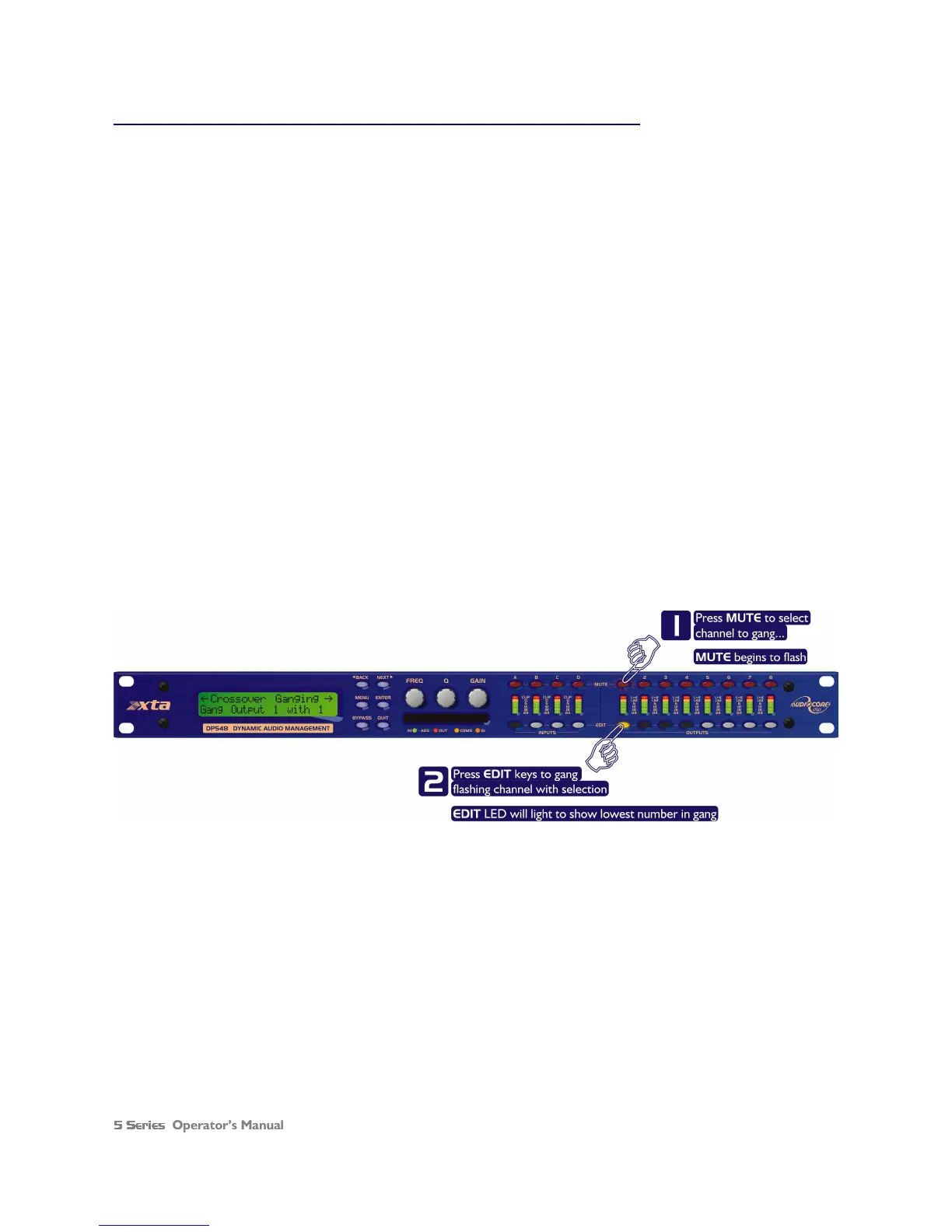
With these rules in mind, selecting and setting up gangs is quite straightforward.
Press a MUTE key to choose the output to gang – its LED will begin to flash, and an EDIT key will illuminate to show
which output it is currently ganged with. To change this selection, just press another EDIT key, remembering that gangs
work from the highest to lowest number. So, to gang outputs 1 and 5, press MUTE 5 then EDIT 1 – the display will show
<
<<
<-
--
-Crossover Ganging
Crossover GangingCrossover Ganging
Crossover Ganging
Gang Output 5 with 1
Gang Output 5 with 1Gang Output 5 with 1
Gang Output 5 with 1
Ganging is cleared by selecting Ganging=None
Ganging=NoneGanging=None
Ganging=None
from the initial choices given above. The
Input Ganging
Input Ganging Input Ganging
Input Ganging
procedure is identical to the crossover ganging, selectable under the
Input Sub
Input SubInput Sub
Input Sub-
--
-Menu
MenuMenu
Menu.
Please note that ganging options shown above refer to the DP548 – the DP544 will obviously not have options for ganging
outputs 5 to 8!