Xtreme Power Conversion Corporaon
P91, TX91, TX91L, TXVR Service Manual
Page 11
Uninterrupble Power Supply
5 Funcon explanaons for each PCB
Table 5.1 PCB informaon
Item PCB Name PCB serial number Quan-
ty
Remark
1
SPS-Charger
6k
71-302390-XXG
1
10k 1
2 CNTL 72-300211-XXG /
71-301569-XXG
1
3 Communicaon 72-300294-XXG/71-302389-XXG
72-300571-XXG/71-303176-XXG
1
4 EMI 6k 71-302448-XXG 1 For 6kVA model
10k 71-302408-XXG 1 For 10kVA model
5 Main Power 6k 71-302114-XXG 1 For 6kVA model
10k 71-301756-XXG 1 For 10kVA model
6 Para(A) 71-302096-XXG 1 They are oponal for
parallel funcon.
Para(B) 71-302097-XXG 1
Para 71-303273-XXG
Just for tower
7 O/P Relay 71-300026-XXG 1
Note: “XX” in the serial number is the version of the PCB. It may be modied according to releasing
version in the future.
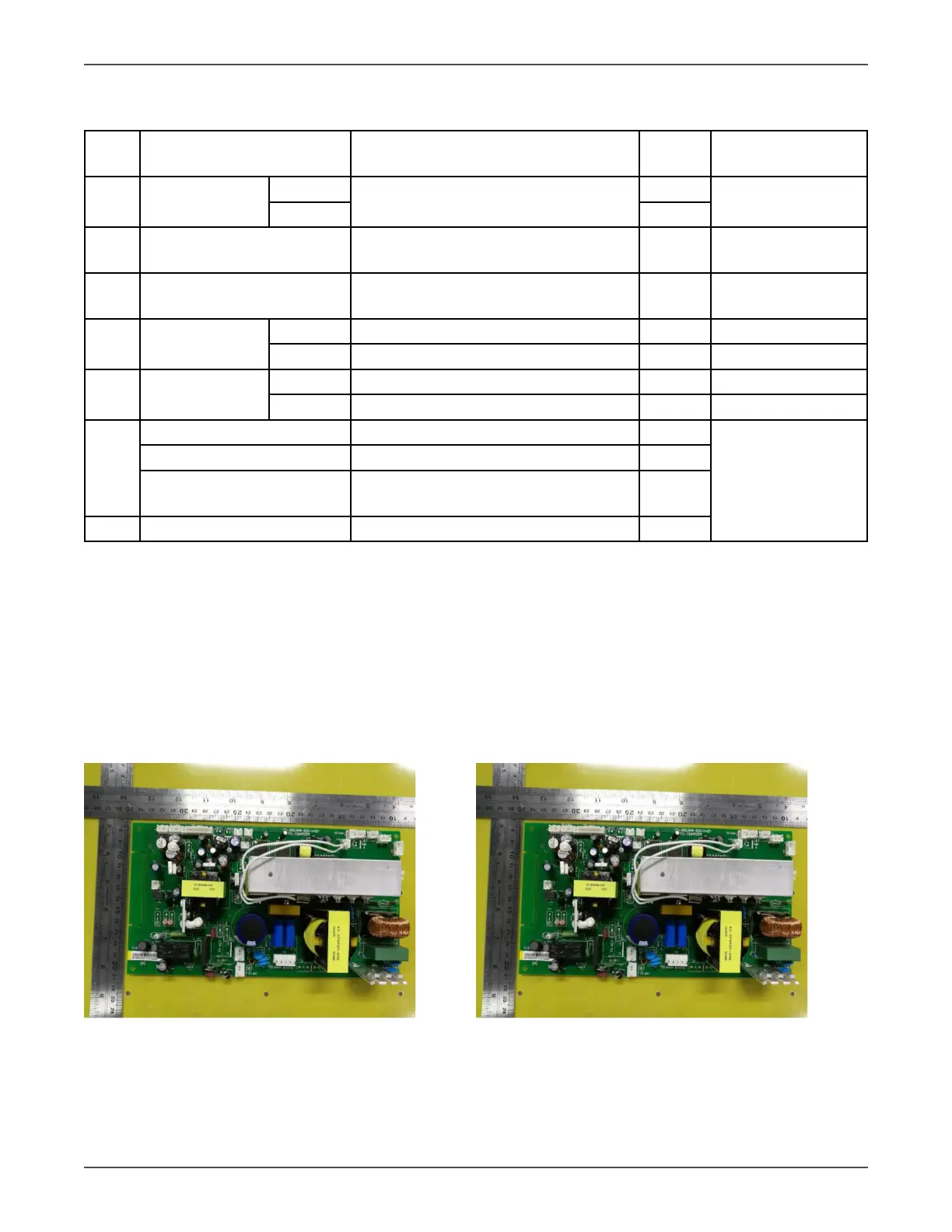
5.1 SPS-Charger board
The SPS-Charger board consists of switch power supply (SPS) and charger. The SPS generates all the
powers needed by dierent circuits.
You can set the charge current to be 1A/2A/3A/4A on LCD by conguring jumpers JP01, JP02, JP03, JP04
and JP05 you can also set charge voltage based on the number of baeries per string