Xtreme Power Conversion Corporaon
P91, TX91, TX91L, TXVR Service Manual
Page 9
Uninterrupble Power Supply
Figure 4.1 is a yback converter. When Q1 is on, all recer diodes (D1/D2/D3) are on open status and all out-
put capacitors (C1/C2/C3) supply currents to the load. The primary coil of the transformer will become a pure
inductor and the primary current will linearly increase to store energy in the coil. When Q1 is o, primary cur-
rent will stop and all recer diodes (D1/D2/D3) will turn to “close” status. It will release the stored energy from
the primary coil of the transformer to the secondary coil to supply loads. At the same me, it will charge output
capacitors including 15V, +12V, +5V, +12V(Fan), and HFPW.
The power of 12V, +5V supplies stable voltage to all kinds of ICs and other devices such as HCT. The
+12V (Fan) is supplied to fans and relays. The HFPW supplies a high frequency power for the switch
(SCR/IGBT) driver and some other drive boards.
4.2 PFC/Booster
N
Q
1
Q
2
U
BUS+
U
BUS-
Utility
Battery
L
1
D
2
D
1
C
1
C
2
N
L
2
Q
3
Q
4
Q
5
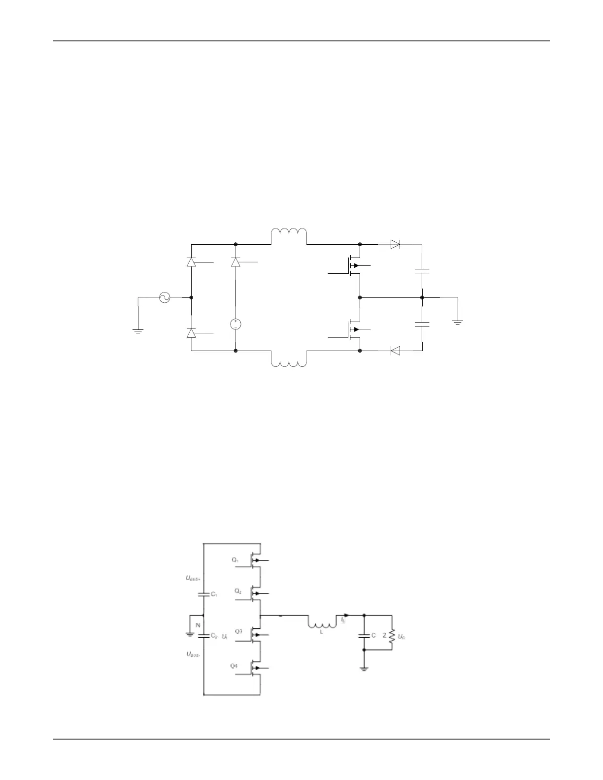
Figure 4.2 PFC/Booster
As shown in the Figure 4.2, when Q1/Q2 is on and D1/D2 is o, the current will increase to store energy in
choke(L1/L2). When the Q1/Q2 is o and D1/D2 is on, the choke will release energy. Therefore, we can control
the current in chokes (input current) by regulang the me of Q1/Q2 on and o.
4.3 Inverter
The input of the three level inverter topology is two DC voltages, and the output is an AC voltage, as shown in
the Figure 4.3. When Q1/Q2 is on and Q/Q3 is o, the voltage of the bridge midpoint is +BUS. When Q1/Q2 is o
and Q3/Q4 is on, the voltage of the midpoint bridge is –BUS. We can get any voltage waveform between ±BUS
voltage from LC lter output by regulang the duty cycle of Q1/Q2/Q3/Q4, including sine wave form.
Figure 4.3 Three level inverter bridge