Xtreme Power Conversion Corporaon
P91, TX91, TX91L, TXVR Service Manual
Page 23
Uninterrupble Power Supply
7.1.3 Troubleshoong
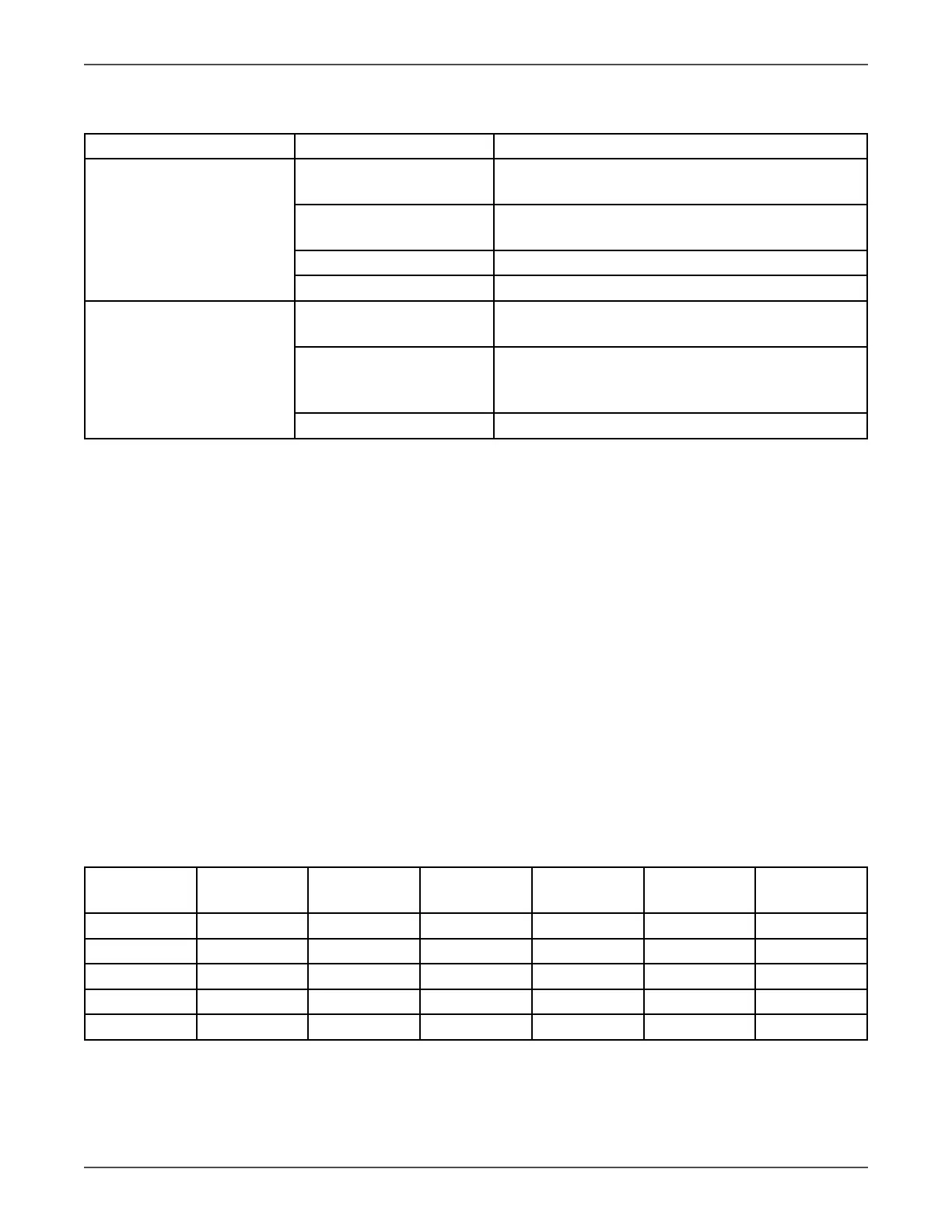
Problem Possible cause Acon
Baery backup me is short Baery not yet been fully
charged.
Keep UPS connected to ulity power connuously
for more than 10 hours to recharge the baeries.
UPS overload. Check the loads and remove some non-crical
loads.
Baery aged Replace the baeries
Charger fails Replace the charger
The UPS cannot power on
aer pressing the buon
The buon is not pressed
and held long enough
Press and hold the buon connuously for more
than 0.5s
Baery is not connected
or baery voltage is too
low, or charger fails.
Check the charger and baery.
UPS failure. Repair the UPS.
7.2 Repair
In this secon, some debug skills are listed to help you nd the failed components and problems as soon as pos-
sible. Before taking the following steps, we strongly suggest reading previous secon for trouble shoong rst.
Then check the components listed in secon 7.2.4 to nd out which block fails
7.2.1 Basic Instruments and tools
1. One computer with RS232 port and one standard RS232 cable;
2. Wire cuers and clamps;
3. One electric soldering iron;
4. One mulmeter;
5. One oscilloscope(voltage and current probe needed);
6. Diagonal pliers, snipe nose pliers, cross screwdrivers (150mm/75mm length), at screwdrivers
(75mm length) and PVC insulang tapes etc;
7. Make-self tools including Balance voltage test equipments, current liming resistors, tubes and clamp ter-
minals with dierent specicaons;
7.2.2 Conguraon of the Model Port on the Control Board
The Model Port (JP1) on the CNTL board should be congured as follows:
Table 7.1 Model Port Seng List
Model Type pin1&pin2 pin3&pin4 Baery
Number
pin5&pin6 pin7&pin8 pin9&pin10
6K 0 1 16 1 0 0
6KL 0 0 17 0 1 1
10K 1 1 18 0 1 0
10KL 1 0 19 0 0 1
20 0 0 0
Note: “1” indicates that the jumper is connected;
“0”indicates that nothing is connected