Xtreme Power Conversion Corporaon
P91, TX91, TX91L, TXVR Service Manual
Page 8
Uninterrupble Power Supply
The Recer and PFC blocks are the input stage of the UPS. The blocks convert AC input power into two stable
DC power stored in the BUS capacitor. In the meanme, PFC (Power Factor Correcon) will be executed and
allows input current tracking the input voltage waveform. Therefore, the input power factor will be corrected to
1 to achieve maximum eciency and produce lowest power polluon to the ulity.
The PFC block in baery mode, also called Booster, is used to convert the low voltage DC power to higher voltage
with stable DC power, stored in the BUS capacitor.
The Inverter block is the output stage of the UPS and used to convert DC power from the BUS capacitor to sine
waveform output power.
When the ulity is within the acceptable range, the UPS will provide power directly from the ulity input and
the Recer and PFC will be executed at the same me. When the ulity is outside of the acceptable range, no
maer it’s because of input voltage or input frequency, the UPS will shut down the Recer and PFC funcons
and turn on the Baery Booster. In case of sudden interrupon from input ulity, the controller can detect the
interrupon in very short me. During the short interval of detecng the interrupon, the output power will be
provided by the power stored in the BUS capacitor. In this way,
there is no any interrupon on output power.
The charger charges the baery when the UPS system is working. Yo u can set the current to be
1A/2A/3A/4A by LCD or command. And you can choose a dierent voltage corresponding to dierent baery
pieces by changing the jumper on the CNTL board, either LCD or command.
The Input EMI secon provides EMI lter funcon. The input EMI lters can prevent the UPS from being
interference by external electronic/magnec noise which is generated by other electronic system and prevent
other systems from the noise generated inside the UPS system.
The SPS generates DC power supply needed by operaon of the circuit of the UPS itself. The Bypass provides
a path that ulity can power the output directly when the Inverter is not executed. The Maintenance Bypass
provides another path that ulity can power the output directly when UPS is in maintenance status.
4. Working Principle of the Major Funconal Block
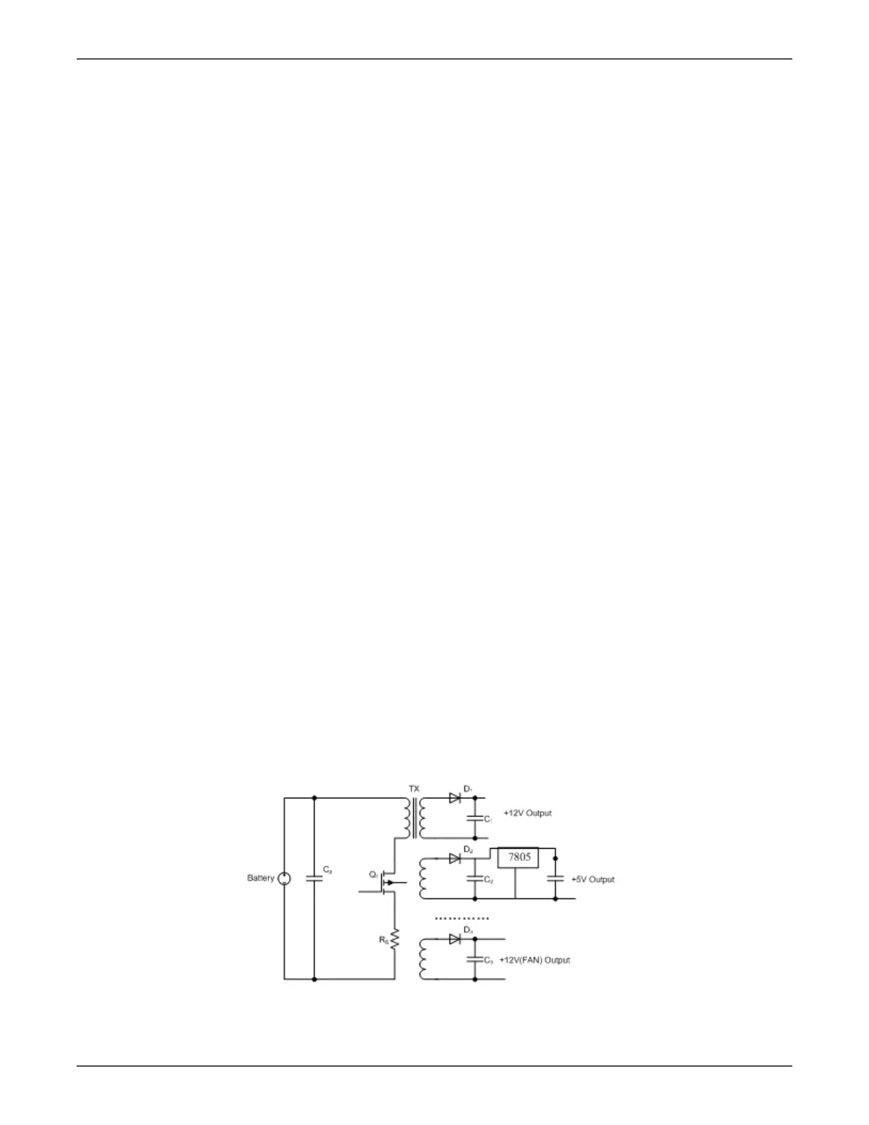
4.1 Switch Power Supply
The Switch Power Supply (SPS) supplies DC power for UPS operaon. The input source of the SPS is the
grid when the grid voltage is higher than 110V . Or the input source of the SPS is the baery.
Figure 4.1 Basic circuit of power supply