29
6.3.3 Control Terminals
All control cables which are connected to the control- or RS485-terminal have to be screened.
If unscreened control cables are used, signal interference may occur and could interfere
to the function and signals of the HYDROVAR.
Don’t connect the ground of the control card to different voltage potentials.
All electronic ground terminals and GND of the RS 485-interface are connected internally.
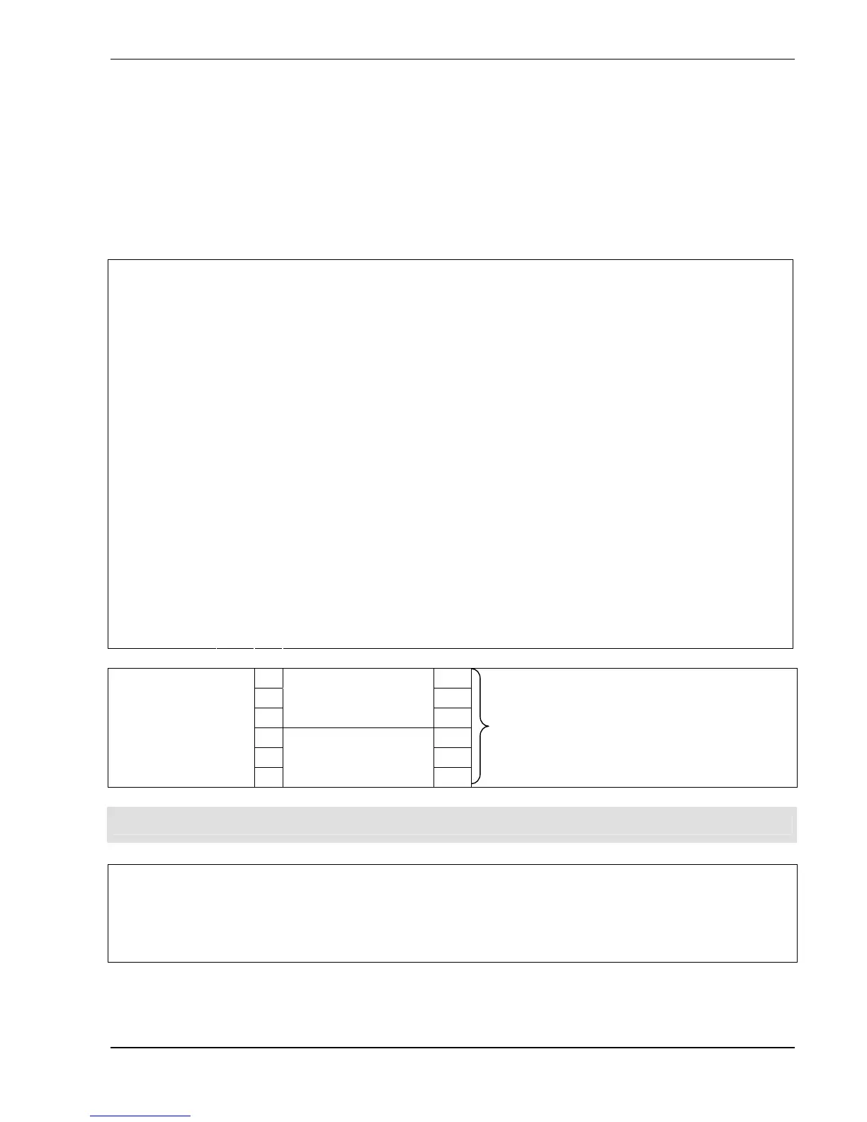
1
Actual value input 4-20mA, [Ri= 50 Ohm]
3
Power supply for external sensor [15VDC, max. 100mA]
4
External on/off (release) [5VDC, Ri=10kOhm]
contacts suitable for switching <10VDC are necessary
6
Low water [5VDC, Ri=10kOhm]
(e.g. incoming pressure switch or water level switch)
8
Thermal switch or PTC
(mounted in the motor terminal box) [5VDC, Ri=10kOhm]
9
GND, electronic ground
11
Analogue output 0-10 VDC, [max. 2mA]
to show actual value or actual frequency
12
Current signal input 4-20mA
to determine the required value or the offset
13
Voltage signal input 0-10VDC or 2-10VDC
to determine the required value or the offset
Terminals:
X1/
14
Digital input for 2
nd
Required value
1
CC
Terminal:
(dry contacts)
X2/
6
NO
[Max. 250VAC]
[Max. 220VDC]
[Max. 30VDC]
[0,3A resistive load]
[0,3A resistive load]
[2A resistive load]
NOTICE! In case of no error, the fault relay (X2/2 - X2/3) is closed!
Terminal: X5 and X6/ 1
RS 485 SIO - LOW
2
RS 485 SIO + HIGH
3
RS 485 GND
4
RS 485 + 5 VDC [max. 20mA]
supply of external interface converter