I/O and Cabling Considerations
3.2.2 Device Wiring Considerations (RJ-45)
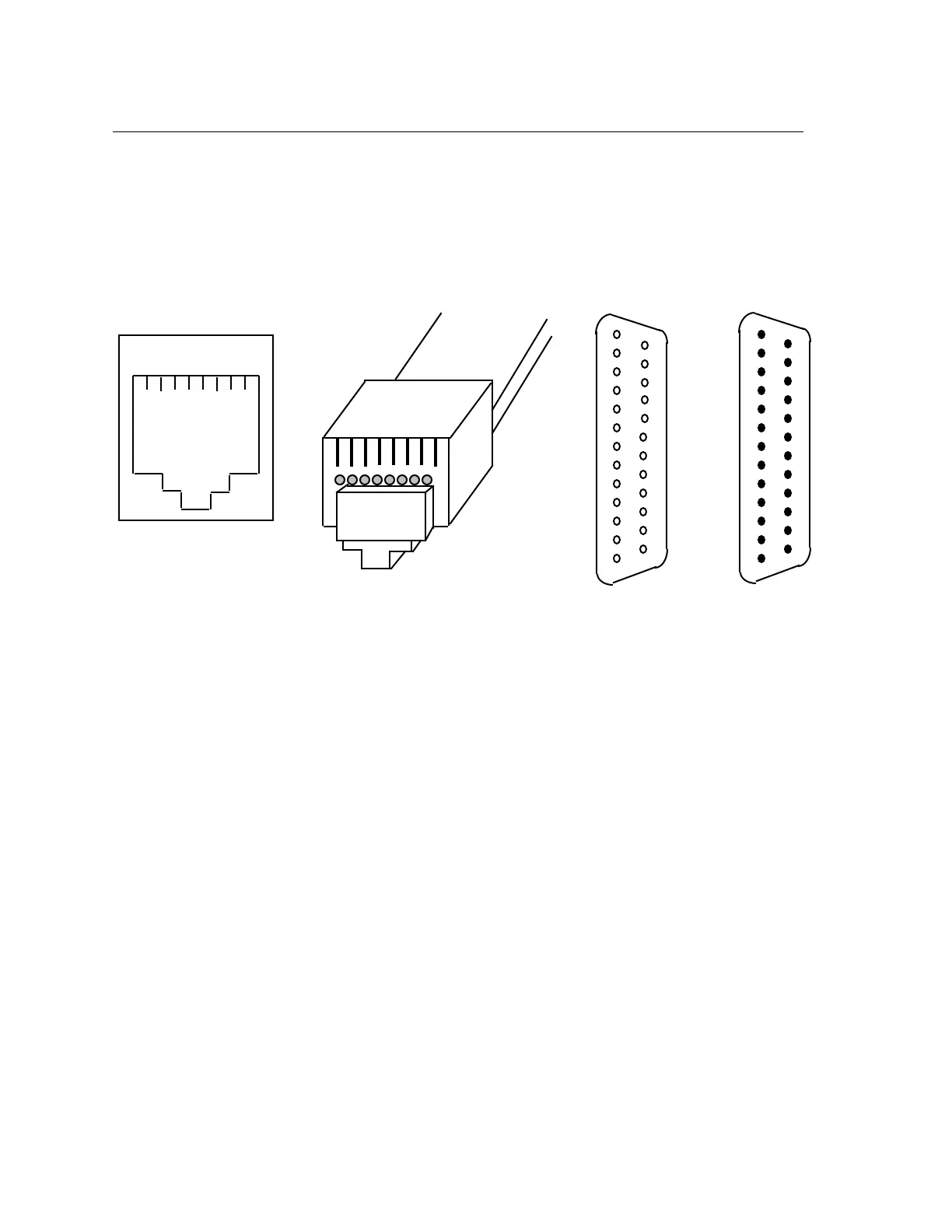
Using the model 723 I/O module, you will normally connect the serial device cables to the 8-pin
RJ-45 jacks on the I/O module. It does not matter which port you connect a device to; the I/O
module provides full support to each port. The female RJ-45 jack shown in Figure 3-2 shows the
signal assignments of the 8-pin jacks.
1 2 3 4 5 6 7 8
RJ-45 Jack
(Female)
1
13
25
14
1
13
14
25
DB-25
(Female)
DB-25
(Male)
8 7 6 5 4 3 2 1
RJ-45 Plug
(Male)
Figure 3-2. RJ-45, DB-25 Pins
Female RJ-45 Pin Signal
1 RNG/CTS (input)
2 DTR (output)
3 XMT (output)
4 XMTGND
5 RCVGND
6 RCV (input)
7 DSR/DCD (input; see note after Figure 3-3)
8 RTS (output)
You should also give special consideration to the wiring scheme when connecting a device
such as a terminal to a serial port. Using modular cabling options (see section 3.2.3), signals
are directed to the correct pins by the adaptor. If you wish to make your own cables, you must
construct the cable with the appropriate wiring scheme. The terminal server is considered a
DTE device.
3-24 0021