Chapter 3: Servo Drive and Motor Connection ES2 Series Servo User Manual Lite V1.0
9
CN5 parameters, etc.
6 Control port CN1 Connect with host controller for IO signal control
7 Encoder feedback port CN2
Connect for motor encoder feedback
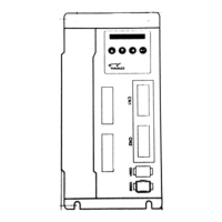
3.2 Main circuit
3.2.1 Introduction of each part
The functions, names and specifications of each part of the main circuit are as follows:
Table 3-2 Servo drive main circuit terminal function specifications
Name Terminal mark
Function, specification
Main circuit
power input
terminal
R、S
Single-phase AC220V power input
R、S、T
Three-phase AC220V power input
Control circuit
power input
terminal
L1C、L2C
Control loop power, input according to specifications
External
regenerative
resistor
connection
terminal
P⊕、D、C
By default, short wires are connected between P⊕-D.
When the braking force is insufficient, please make an open
circuit between P⊕-D.
(remove the short wiring) and connect external braking resistor
between P⊕-C
External braking resistors should be purchased separately.
Common DC
terminal
P⊕、 ○
一
Servo DC bus terminal for common bus connection when
multiple units are connected in parallel
Servo motor
connection
terminal
U、V、W
The servo motor connection terminal, connected to the U, V, W
of the motor.
Ground
terminal
PE
Two grounding terminals are connected to the power grounding
terminal and the motor grounding terminal.
Be sure to ground the entire system.
3.3 Encoder interface
The encoder line PIN distribution diagram is as follows:
Table 3-3 Encoder line PIN distribution diagram
PIN 2500 line encoder signal Functional description
1 A+
Encoder signal
2 A-
3 B+
4 B-
5 Z+
6 Z-
7 +5V +5V power output
8 GND Power GND output
9 --
Shell PE
 Loading...