Chapter 4: Operation and Adjustment
In YAKO servo
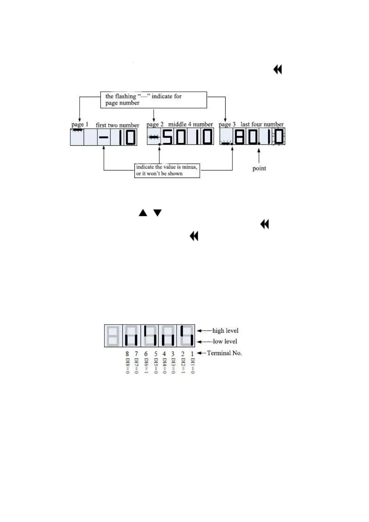
system, the display is performed by a method of displaying 4 digits by 3 pages. At
this time, there is a flashing
to indicate the screen number of the current character.
For example, if the parameter value to be displayed is
pages as [-
below:
When using the SHIFT button to shift, it will automatically switch to the corresponding display
segment. For example, suppose the current flashing bit is thousand. When using SHIFT, it will
automatically sw
itch to the middle four digit display, and the 10,000 digit (that is, the rightmost digit of
this segment) will flash. Press
parameters that can be modified, the corresponding modifications can be
read-
only parameter, you can only use the long press
4.1.3
Monitorable parameter list
The monitor display is a function for displaying the command value set in the servo driver, the state of
the
input/output signal, and the internal state of the servo driver. The monitor display function code
table is as follows.
Note: DI/DO terminal status display method
1. A
digital tube displays two DI/DO
low position
2.
The status of DIDO is represented by 8 status bits. Currently, the standard DI is 8 channels and
DO is 5 channels. The figure below shows the status
The meaning of the above figure are as follows:
DI6=1;DI7=0;DI8=0。
Chapter 4: Operation and Adjustment
ES2 Series Servo User Manual Lite V1.0
22
system, the display is performed by a method of displaying 4 digits by 3 pages. At
this time, there is a flashing
“—“ segment in the
leftmost character of each screen, which is used
to indicate the screen number of the current character.
For example, if the parameter value to be displayed is
-
10501080.10, it will be divided into three
to show in the screen. A
When using the SHIFT button to shift, it will automatically switch to the corresponding display
segment. For example, suppose the current flashing bit is thousand. When using SHIFT, it will
itch to the middle four digit display, and the 10,000 digit (that is, the rightmost digit of
this segment) will flash. Press
/
at this time, the increase or decrease is 10000. For the
parameters that can be modified, the corresponding modifications can be
made by
only parameter, you can only use the long press
key to scroll through the page.
Monitorable parameter list
The monitor display is a function for displaying the command value set in the servo driver, the state of
input/output signal, and the internal state of the servo driver. The monitor display function code
Note: DI/DO terminal status display method
digital tube displays two DI/DO
, the short “|” in high position
low level. All indications correspond to the physical DI/DO.
The status of DIDO is represented by 8 status bits. Currently, the standard DI is 8 channels and
DO is 5 channels. The figure below shows the status
of the DI input terminal.
The meaning of the above figure are as follows:
DI1=0;DI2=1;DI3=0
ES2 Series Servo User Manual Lite V1.0
system, the display is performed by a method of displaying 4 digits by 3 pages. At
leftmost character of each screen, which is used
10501080.10, it will be divided into three
. As shown
When using the SHIFT button to shift, it will automatically switch to the corresponding display
segment. For example, suppose the current flashing bit is thousand. When using SHIFT, it will
itch to the middle four digit display, and the 10,000 digit (that is, the rightmost digit of
at this time, the increase or decrease is 10000. For the
shifting. If it is a
key to scroll through the page.
The monitor display is a function for displaying the command value set in the servo driver, the state of
input/output signal, and the internal state of the servo driver. The monitor display function code
evel and
low level. All indications correspond to the physical DI/DO.
The status of DIDO is represented by 8 status bits. Currently, the standard DI is 8 channels and
DI4=0;DI5=0;
 Loading...