Chapter 3: Servo Drive and Motor Connection
Chapter 3:
Servo Drive and Motor Connection
3.1
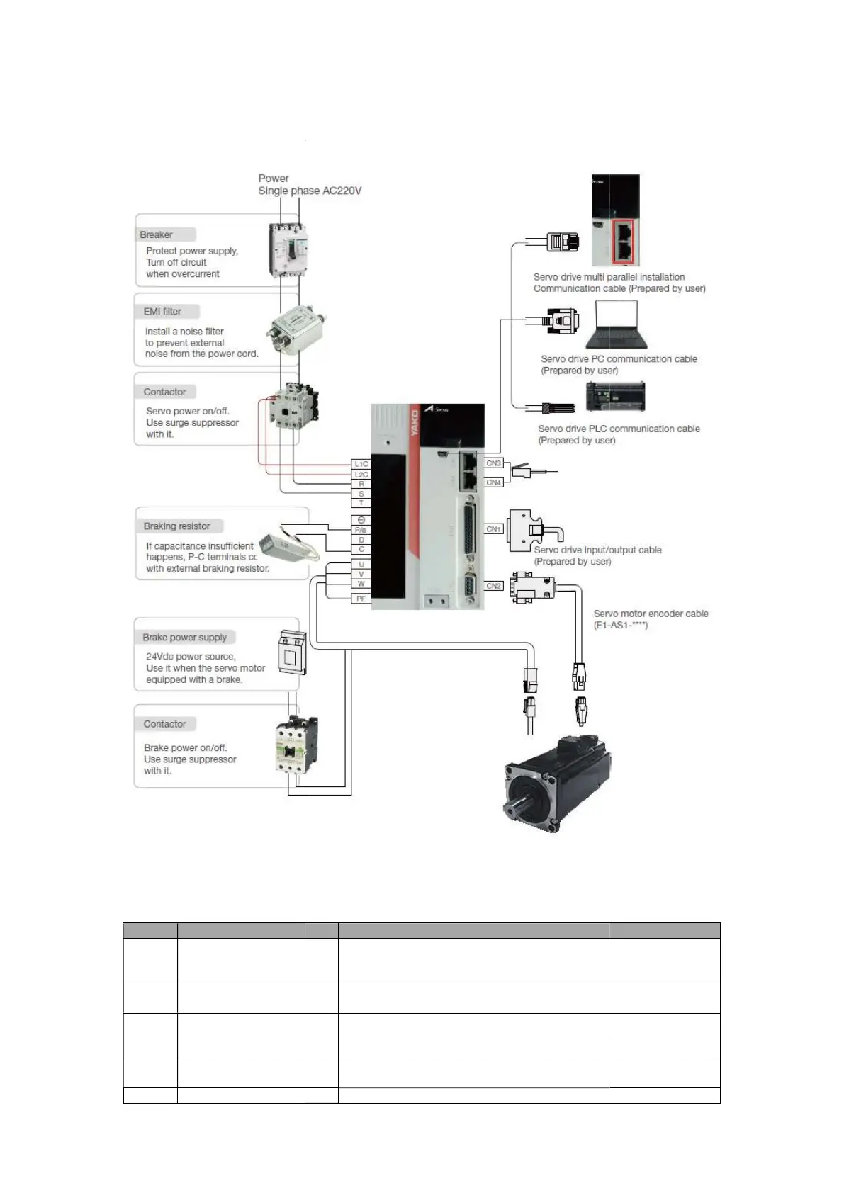
Figure 3-
1 System structure diagram
The names, functions and specifications of each part of the drive are as follows.
Table 3
No. Name
1
L1C, L2C
terminal
2
R, S, T
AC
3
P⊕, D, C
External regenerative
resistor terminal
4
U, V, W, PE
Motor power
5
Chapter 3: Servo Drive and Motor Connection
ES2 Series Servo User Manual Lite V1.0
8
Servo Drive and Motor Connection
1 System structure diagram
The names, functions and specifications of each part of the drive are as follows.
1 Servo drive main circuit terminal name and function
Description
Input control circuit power according to s
Input main circuit power according to specifications
The default wiring is P connected with D. When using an external ⊕
regenerative resistor, disconnect P and D⊕ first
external regenerative resistor between P and C.⊕
Connect servo motor three-phase and ground wire
Connect to the PC via Mini USB to monitor, run tests, change
ES2 Series Servo User Manual Lite V1.0
1 Servo drive main circuit terminal name and function
Input main circuit power according to specifications
The default wiring is P connected with D. When using an external ⊕
Connect to the PC via Mini USB to monitor, run tests, change
 Loading...