218 Chapter 18—Digital I/O
03D—Owner’s Manual
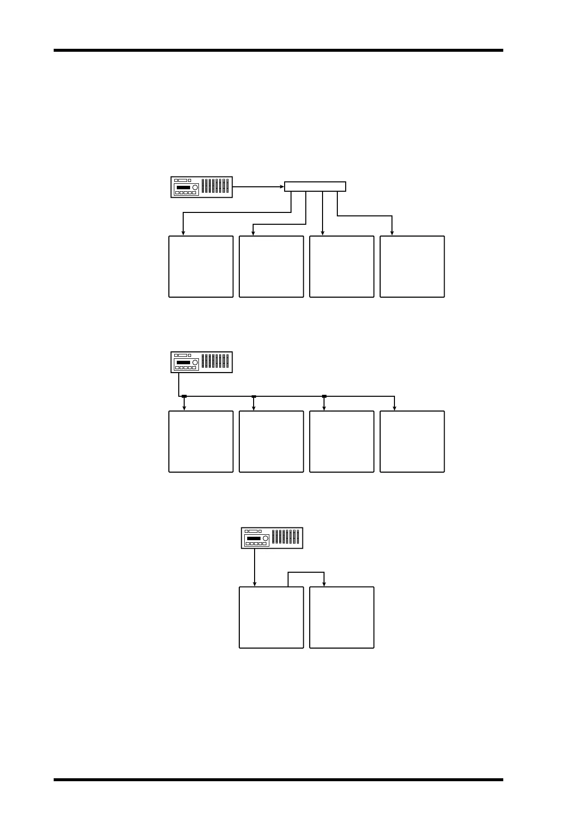
Wordclock Connections & Termination
For correct operation it is essential that wordclock cabling be terminated correctly. The
03D has a wordclock termination ON/OFF (75Ω) switch on the rear panel. Wordclock
is a TTL signal, and IN and OUT connections use BNC connectors. Three wordclock
distribution examples are shown below. Note the 75Ω wordclock terminator switch set-
tings.
1. Parallel Distribution with IFU4 Interface Unit
In this example, an Yamaha IFU4 Interface Unit is used to distribute the wordclock sig-
nal among devices. All wordclock terminator switches are set to ON.
2. Using BNC T-bar Connectors
This example is similar to the above except that T-bar connectors are used. In this sys-
tem, only the last device’s wordclock terminator switch is set to ON.
3. Daisy Chain Distribution
In this example, the wordclock master is a digital multitrack recorder. Both 03D word-
clock terminator switches are set to ON. This method of wordclock distribution is not
recommended for large systems.
03D-A
75Ω Switch=ON
03D-B
75Ω Switch=ON
Other
Device-A
75Ω Switch=ON
Other
Device-B
75Ω Switch=ON
WORDCLOCK
OUT
WORDCLOCK IN WORDCLOCK IN WORDCLOCK IN WORDCLOCK IN
YAMAHA IFU4
03D-A
75Ω Switch=OFF
03D-B
75Ω Switch=OFF
Other
Device-A
75Ω Switch=OFF
Other
Device-B
75Ω Switch=ON
WORDCLOCK
OUT
WORDCLOCK IN WORDCLOCK IN WORDCLOCK IN WORDCLOCK IN
03D-A
75Ω Switch=ON
IN OUT
03D-B
75Ω Switch=ON
WORDCLOCK
OUT
WORDCLOCK
IN OUT
WORDCLOCK
 Loading...