CB301
IC301
IC301
IC302
IC302
IC303
IC303
CB305
W3004
W3002
W3001
W3003
W3005
W3006
A
1
2
3
4
5
6
7
8
9
10
BCDEFGH I JK
L MN
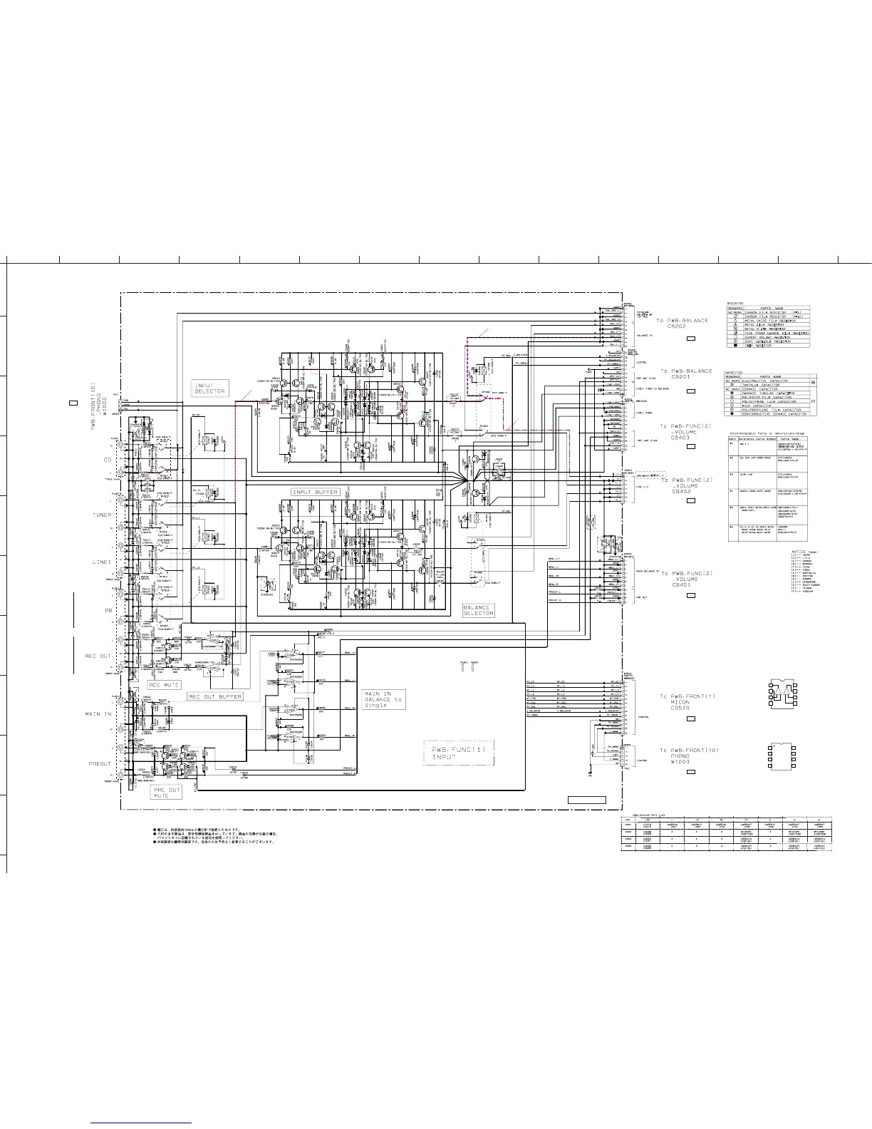
A-S2000
60
★ All voltages are measured with a 10MΩ/V DC electronic voltmeter.
★ Components having special characteristics are marked s and must be replaced
with parts having specifications equal to those originally installed.
★ Schematic diagram is subject to change without notice.
FUNCTION 1/3
12.0
-11.9
-11.9
-11.9
-11.8
-11.9
-11.9
0
0
-11.8
0
0
-11.8
0
0
0
0
0
-12.5
0
12.6
0
0
0
0
0
0
12.6
-12.5
0
0
0
-12.6
0
0
0
12.6
0
0
-11.8
0
0
-11.8
0
0
-11.8
0
0
-11.8
25.7
5.8
0.3
0.3
0.1
0.3
25.6
0.9
0
1.0
0.9
0
0.5
1.1
24.6
25.1
0.9
0.3
0
6.4
24.6
5.8
24.6
1.1
24.6
25.7
-0.9
0
-25.6
-24.5
-24.5
1.1
0.6
25.7
-11.9
-11.9
-11.9
-11.9
0
-0.6
-25.6
25.7
0.6
25.7
0.6
0
-25.6
0.5
0
0.5
-25.6
0.9
1.1
-0.6
0.2
-0.9
-0.4
0.5
-0.1
6.3
5.8
5.8
-0.9 -25.0
-24.8
-25.6
-0.6
0
0
0.3
0.3
0.3
5.8
5.8
25.7
5.8
0.3
0.3
0.1
0.3
24.6
0.9
0
1.3
0.9
0
0.5
1.1
24.6
25.1
0.9
0.3
0
6.4
24.6
5.8
25.7
1.1
25.2
24.6
25.7
-0.9
0.3
-25.6
-24.5
-24.5
1.1
0.5
25.7
0
-0.6
-25.6
0.9
1.1
0
-0.6
0.3
-0.9
-0.3
0.5
0.5
6.3
5.8
5.8
-0.9
-25.1
-24.8
-25.5
-0.6
0
0.1
0.3
0.3
0.3
5.8
5.8
-11.9
CD L
IN L
CD BAL L
FUNCTION (1)
LINE 2
IC301: NJM2068MD-TE2
Dual operational amplifier
OUT1
OUT2
–IN1
+IN1
+IN2
-IN2
–VCC
+VCC
1
2
3
4
8
7
6
5
+
–
+
–
IC302, 303: OP275GSR
Dual bipolar/JFET, audio operational amplifier
OUT A
-IN A
V-
V+
OUT B
1
2
3
4
5
+IN A -IN B
+IN B
6
7
8
to BALANCE_CB201
Page 59
I5
to FUNCTION (2)_CB403
Page 61
J4
to FUNCTION (2)_CB402
Page 61 B6
to FUNCTION (2)_CB401
Page 61
B5
to FRONT (1)_CB519
Page 64
B5
to FRONT (10)_W1003
Page 65 B5
to BALANCE_CB202
Page 59
I7
to FRONT (10)_W1002
Page 65
M5