Support for Shure AXT400, QLXD4 and ULXD4
V4.1 Supplementary Manual
8
This assigns the output signal from the AXT400 to the input channel, and at the same
time allows you to control and monitor the level of the AXT400 from the input channel.
For Shure QLXD4/ULXD4
Refer to “Remotely controlling WIRELESS unit” in the CL series or QL series Reference
Manual.
For QLXD4, the PORT ASSIGN tabs have been added. The MUTE button is not displayed.
For ULXD4, the PORT ASSIGN tabs have been added.
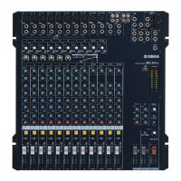
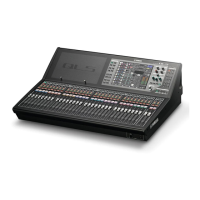
GAIN/PATCH window (1ch)
For Shure AXT400 / QLXD4/ULXD4
1
Frequency
Indicates the frequency that is currently set for the RF signal.
2 TX.GAIN knob
Sets the gain for the transmitter. To adjust the value, press the knob to select it, and use
the multifunction knobs (for CL series consoles) or the TOUCH AND TURN knob (for CL/
QL series consoles).
NOTE
• When the AXT400 is connected via a ShowLink® remote control, a gray circle is displayed here
instead of a knob, and the gain cannot be adjusted.
• For QLXD4/ULXD4, a gray circle is displayed instead of the knob, and you cannot adjust the gain.
3 RX.LEVEL knob (for AXT40)
RX.GAIN knob (for QLXD4/ULXD4)
Sets the gain for the receiver. To adjust the value, press the knob to select it, and use the
multifunction knobs (for CL series consoles) or the TOUCH AND TURN knob (for CL/QL
series consoles). The level meter located at the immediate right of the knob indicates
the input level.
4 MUTE indicator
Indicates the mute status (on/off) of the audio signal for the receiver.
NOTE
For QLXD4, the MUTE button is not displayed.
5 RF (Radio Frequency) signal meter
Shows bars to indicate the level of the RF signal (both A and B channels for AXT400).
An active antenna indicator is shown on the right side. It indicates which antenna is
enabled.
NOTE
For details about the relationship between the number of bars and the actual strength of the RF
signal, refer to the manual from Shure.
6 Battery indicator
Shows bars to indicate the remaining battery power.
NOTE
For details about the relationship between the number of bars and maximum operation time, refer
to the manual from Shure.
 Loading...