When installing the optional Plug-in board (from when you
remove the cover to when the cover is replaced securely)
all operations must be done with the AC power cord
disconnected.
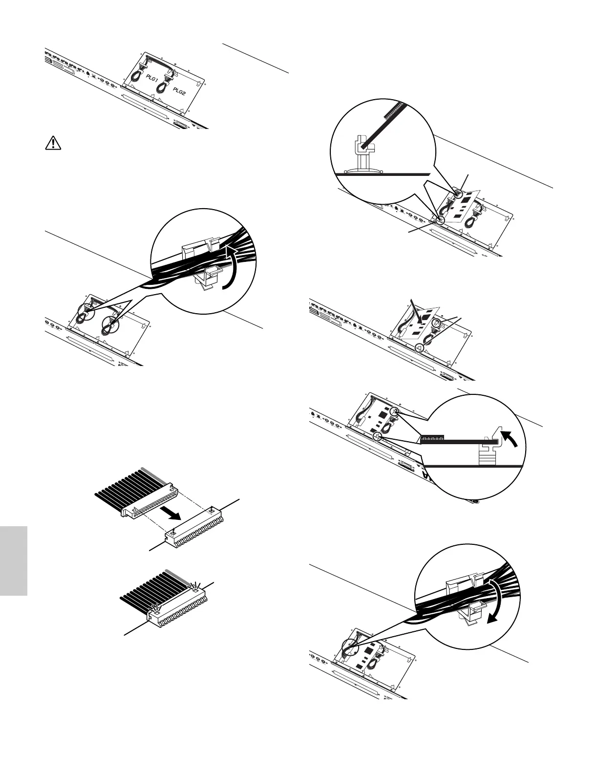
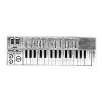
5 Remove the cable from the hook-shaped bundle tie on the
plate.
6 Take out the Plug-in board from the anti-static bag.
When installing the board, the side with a connector and
ICs must be on top.
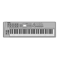
7 Carefully plug the cable connector into the Plug-in board
connector until the two notches on the cable connector
lock into the sockets on the board as shown in the
illustration.
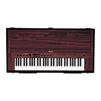
8 Mount the Plug-in board onto the plate as detailed in the
following steps.
8-1 Insert one side of the Plug-in board (the connector
side) into the hooks 1 as shown in the illustration.
8
-2 Press down the other side until it is securely
settled on the hooks 2.
9 Fix the connector cable to the hook-shaped bundle tie on
the plate.
) Replace the Plug-in board cover by fastening the eight
flat-head screws you removed in the step 3 above.
Use a coin or a Phillips screwdriver to secure the cover.