19
DSP-A595a
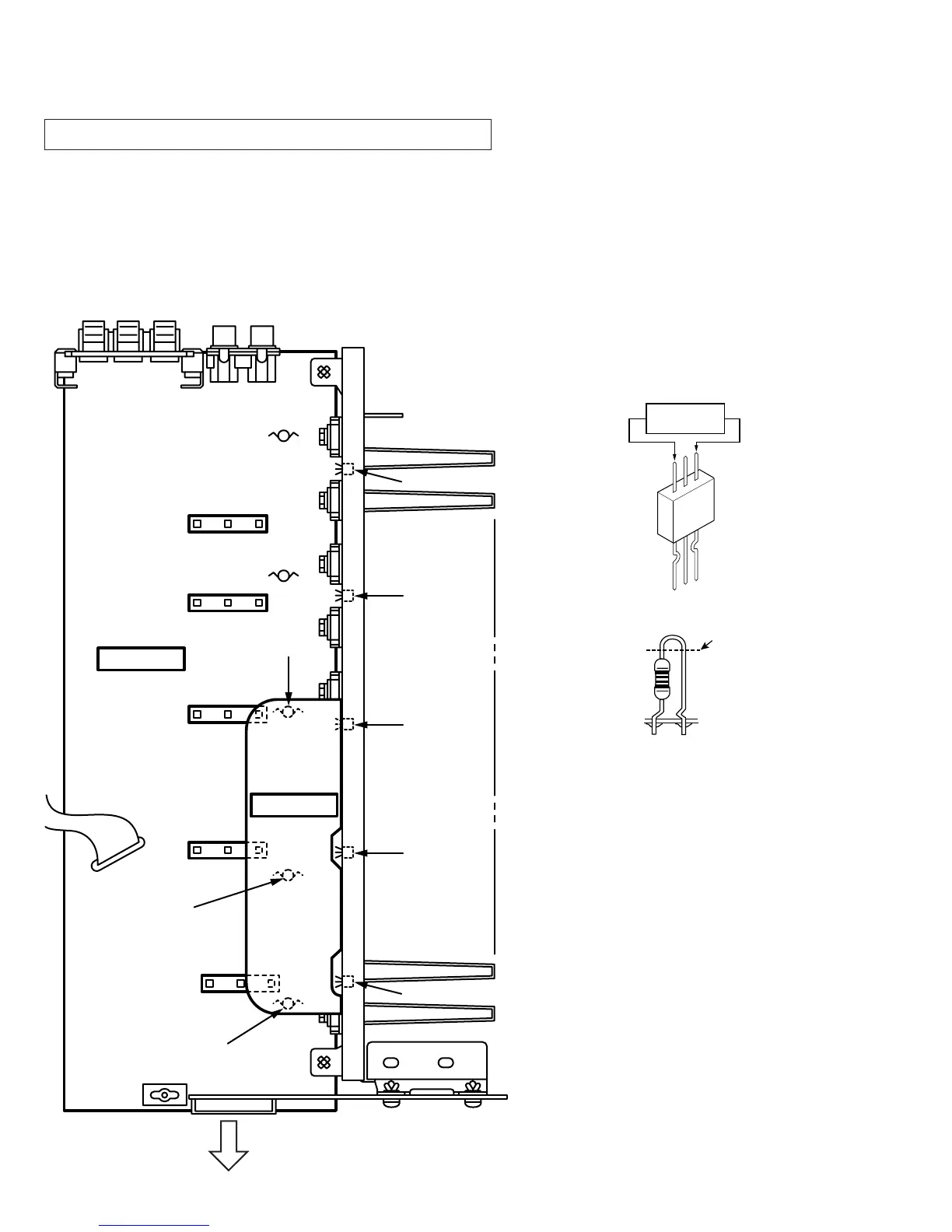
Confirmation of Idling Current of Main Amplifier
•
Right after power is turned on, confirm that the voltage across the
terminals of R688(Main Lch),R690(Main Rch), R692(Center),
R694(Rear Lch), R696(Rear Rch) are between 0.1mVand 5.0mV.
•
If it exceeds 5.0mV, open (cut off) R571 (Main Lch), R577 (Main
Rch), R589 (Center), R595 (Rear Lch), R583 (Rear Rch) and
reconfirm the voltage again.
•
Confirm that the voltage is 0.25mV ~ 15.0mV after 60 minutes.
■ AMP ADJUSTMENT
Note)
•
If R571, R577, R589, R595 and
R583 have already been cut off
and idling current does not flow,
reconnect R571, R577, R589,
R595 and R583.
•
Q521 ~ Q525 are transistors for
temperature correction.
Apply silicone grease to contact
surface with the heat sink.
R571(Lch)
R577(Rch)
R589(Cch)
R595(RLch)
R583(RRch)
R583
R692
R595
R589
MAIN
(
1
)
MAIN
(
7
)
Q523
Q525
Q524
Q522
Q521
R696
R694
R690
R688
R577
R571
Front Panel
R688(Lch)
R690(Rch)
R692(Cch)
R694(RLch)
R696(RRch)
Cut off