DSP-A595a
H
47
BACDEFG
1
2
3
4
5
6
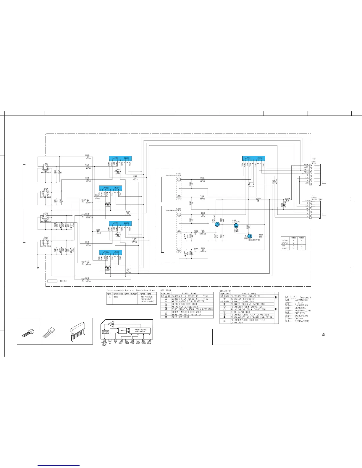
■ SCHEMATIC DIAGRAM (VIDEO)
48
E-48/J-46
E-49/J-47
★
All voltages are measured with a 10M
Ω
/V DC electric volt meter.
★
Components having special characteristics are marked and
must be replaced with parts having specifications equal to those
originally installed.
★
Schematic diagram is subject to change without notice.
Conditions
• INPUT → CD
• VOLUME → minimum(–∞)
• IMPEDANCE
SELECTOR → Upper
• PRO LOGIC → On
PIN CONNECTION DIAGRAM OF
TRANSISTORS AND IC’s.
LA7956
2SC1740S(R,S)
2SC1815(Y)
E
C
B
E
C
B
IC301~305 : LA7956
Video Switch
DVD/LD
VIDEO
SIGNAL
TV/DBS
VIDEO
VCR
IN
VCR
OUT
MONITOR
OUT
DVD/LD
VIDEO
SIGNAL
S VIDEO
VCR
IN
VCR
OUT
MONITOR
OUT
TO INPUT (1)
CB101
page E-50/J-48
C-8
TO OPE (2)
CB807
page E-52/J-50
J-2
VIDEO
S-VIDEO SELECTOR
& AMP
VIDEO SELECTOR
& AMP
3.8
3.8
10.8
0
4.5
0
5.2
3.8
3.8
3.8
10.8
0
4.5
0
5.2
3.8
3.8
10.8
0
4.5
0
5.3
3.8
3.8
10.8
0
4.5
0
5.3
3.8
11.6
6.0 6.0 6.0
7.0
0
0
6.5
5.3
3.8
3.8
11.6
3.8
0
3.8
4.5
0
6.0

 Loading...


