EasyManuals Logo

Yamaha DSP-AX861 User Manual

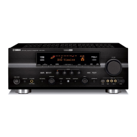
Yamaha DSP-AX861
143 pages
To Next Page IconTo Next Page
To Previous Page IconTo Previous Page
Page #66 background imageLoading...
Page #66 background image
66
RX-V861/HTR-6080/DSP-AX861SE/DSP-AX861
RX-V861/HTR-6080/DSP-AX861SE/
DSP-AX861
52
Display
controller
Segment
digit
select/
output
circuit
Serial
receive
circuit
Digit
output
circuit
Clock
generator
DIG11/
SEG42
51
DIG12/
SEG41
50
DIG13/
SEG40
49
DIG14/
SEG39
48
DIG15/
SEG38
47
DIG16/
SEG37
46
DIG17/
SEG36
45
SEG35
XOUT
6
Vcc1
8
Vcc2
18
Vss
5
Vp
64
XIN
7
CS
SCK
3
SDATA
4
RESET
1
SEG00
44
9
SEG34
SEG26
17
19
SEG25
Segment
output
circuit
Display code
RAM
(8-bit x 60)
CGROM
(35 bit x 166)
CGROM
(35 bit x 16)
code
select
Code
write
Code/
command
control
circuit
DIG00
63
53
DIG10
2
data
timing
clock
dot data
write
scan pulse
17 18 19 20 21 22 23 24 25 26 27 28 29 323130
33
34
35
36
37
38
39
40
41
42
43
44
45
46
47
48
51 495052535455565758596061626364
1
2
3
4
5
6
7
8
9
10
11
12
13
14
15
16
V
P
D
IG
00
D
IG
01
D
IG
02
D
IG
03
S
E
G
12
S
E
G
13
S
E
G
14
S
E
G
15
S
E
G
16
S
E
G
17
S
E
G
18
S
E
G
19
S
E
G
20
S
E
G
21
S
E
G
22
S
E
G
23
S
E
G
24
S
E
G
25
V
cc2
S
E
G
26
R
E
S
E
T
C
S
S
C
K
S
D
A
TA
V
ss
X
O
U
T
X
IN
V
cc1
S
E
G
34
S
E
G
33
S
E
G
32
S
E
G
31
S
E
G
30
S
E
G
29
S
E
G
27
S
E
G
28
D
IG
07
D
IG
08
D
IG
09
D
IG
10
D
IG
11/S
E
G
42
D
IG
12/S
E
G
41
D
IG
13/S
E
G
40
D
IG
14/S
E
G
39
SEG06
SEG05
SEG04
SEG03
SEG02
SEG07
DIG16/SEG37
DIG17/SEG36
SEG35
SEG11
SEG09
SEG10
SEG08
DIG15/SEG38
SEG00
SEG01
D
IG
04
D
IG
05
D
IG
06
IC401 : M66003-0131FP (OPERATION P.C.B.)
FL display driver

Table of Contents

Questions and Answers:

Question and Answer IconNeed help?

Do you have a question about the Yamaha DSP-AX861 and is the answer not in the manual?

Yamaha DSP-AX861 Specifications

General IconGeneral
BrandYamaha
ModelDSP-AX861
CategoryReceiver
LanguageEnglish

Related product manuals