EasyManua.ls Logo

Yamaha LB50IIAC - Yamaha Autolube Pump Inspection

Yamaha LB50IIAC
165 pages
Print Icon
To Next Page IconTo Next Page
To Previous Page IconTo Previous Page
Loading...
Autolube
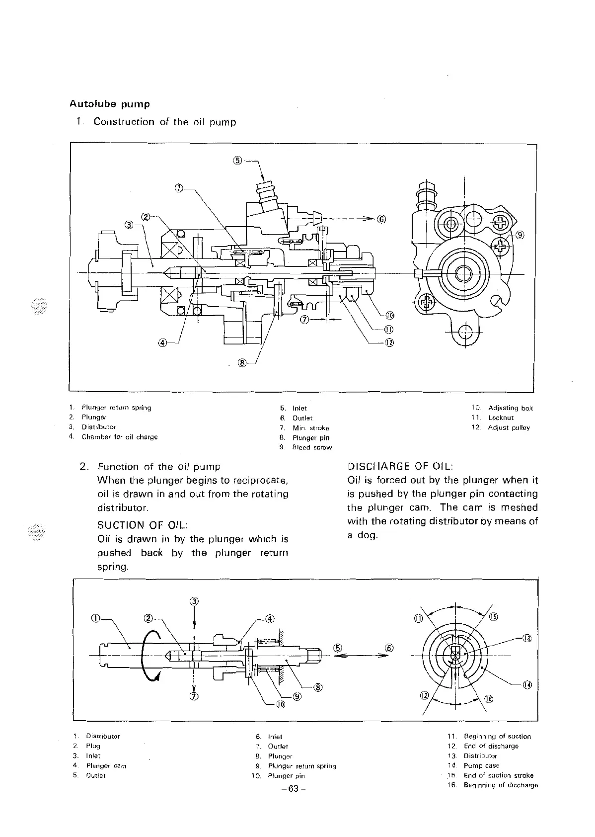
pump
1.
Construction
of
the
oil
pump
CD
---------@
@
1.
Plunger
return
spring
5.
Inlet
2.
Plunger
6.
Outlet
3.
Distributor
7.
Min.
stroke
4
Chamber
for
oil
charge
8. Plunger
pin
9 8 leed
screw
2
3
2. Function
of
the
oil
pump
When
the
plunger
begins
to
reciprocate,
oil is
drawn
in and
out
from
the
rotating
distributor.
SUCTION OF OIL:
Oil is
drawn
in
by
the
plunger
which
is
pushed back
by
the
plunger
return
spring.
CD
®
r
®
}
CV
@
Distributor
6.
Inlet
Plug
7.
Outlet
Inlet
8. Plunger
®
®
4 Plunger cam
9
Plunger
return
spring
5
Outlet
10
Plunger
pin
-63-
@
l)J)
@
DISCHARGE
OF
OIL:
1 0.
Adjusting
bolt
11. Locknut
12.
Adjust
pulley
Oil is forced
out
by
the
plunger
when
it
is pushed
by
the
plunger
pin
contacting
the
plunger
cam. The cam
is
meshed
with
the
rotating
distributor
by means
of
a dog.
®
11
Beginning
of
suction
12
End
of
discharge
13
Distributor
14
Pump
case
15.
End
of
suction
stroke
16
Beginning
of
discharge

Table of Contents