13
MW10
3. MAIN Circuit Board
(Time required: About 14 minutes)
3-1 Remove the bottom case. (See procedure 1.)
3-2 Remove USB circuit board. (See procedure 2.)
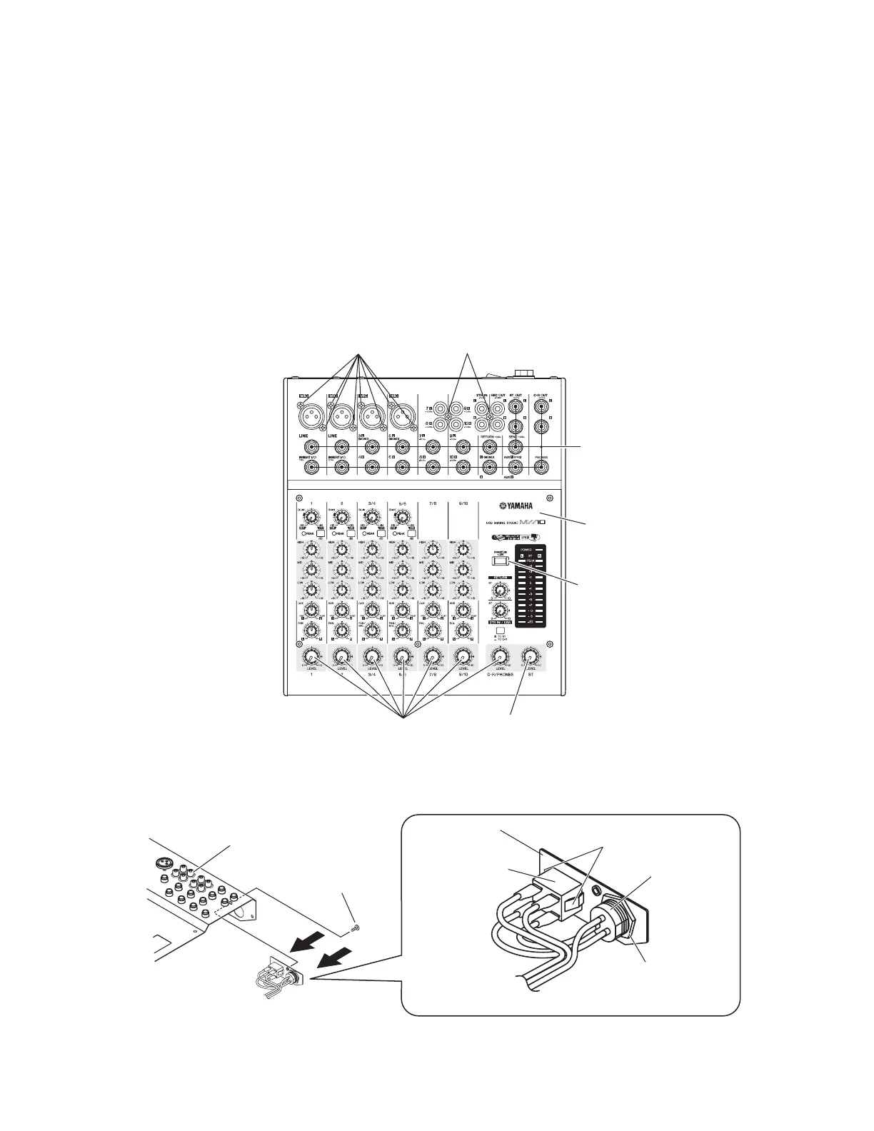
3-3 Remove the one (1) LEVEL knob (red). (Fig.4)
3-4 Remove the seven (7) LEVEL knob (white). (Fig.4)
3-5 Remove the one (1) screw marked [263], and pull out the
power switch and AC connector from the holes on the rear
of the top cover. (Fig.5)
3-6 Remove the eight (8) screws marked [180A]. (Fig.4)
3-7 Remove the two (2) screws marked [180B]. (Fig.4)
3-8 Remove the twenty-one (21) sets of the hexagon nut and
washer using a box wrench. (Fig.4)
3. MAINシート
(所要時間:約14分)
3-1 ボトムケースを外します。(1項参照)
3-2 USBシートを外します。(2項参照)
3-3 ノブLEVEL(赤)〈ST〉1個を外します。(Fig.4)
3-4 ノブLEVEL(白)〈1、2、3/4、5/6、7/8、9/10、C-R/
PHONES〉7個を外します。(Fig.4)
3-5 [263]のネジ1本を外し、電 源スイッチとA Cコネクターをトッ
プカバ ー のリア側の穴から外します。(Fig.5)
3-6 [180A]のネジ8本を外します。(Fig.4)
3-7 [180B]のネジ2本を外します。(Fig.4)
3-8 六角ナットとワッシャ2 1セットをボックスレンチ で 外します 。
(Fig.4)
Hexagonal nut & Washer
(六角ナット、ワッシャー)
Claw
(ツメ)
AC connector
(ACコネクター)
Power switch
(電源スイッチ)
Top Cover
(トップカバー)
[263]
Support AC
(サポートAC)
(Fig.4)
(Fig.5)
[180]: Bonding Tapping Screw-B 3.0X10 MFZN2W3 (WG349000) Bタイト+BOND
[263]: Bind Head Tapping Screw-S 3.0X6 MFZN2W3 (WE877900) Sタイト+BIND
Top Cover
(トップカバー)
Guard, PFL
(ガードPFL)
[180A] [180B]
Hexagon nut & washer
(六角ナット、ワッシャー)
LEVEL knobs (WHITE)
(ノブLEVEL(白))
LEVEL knob (RED)
(ノブLEVEL(赤))
 Loading...