48 Chapter 4: Auxiliaries and Effects
ProMix 01 User’s Guide
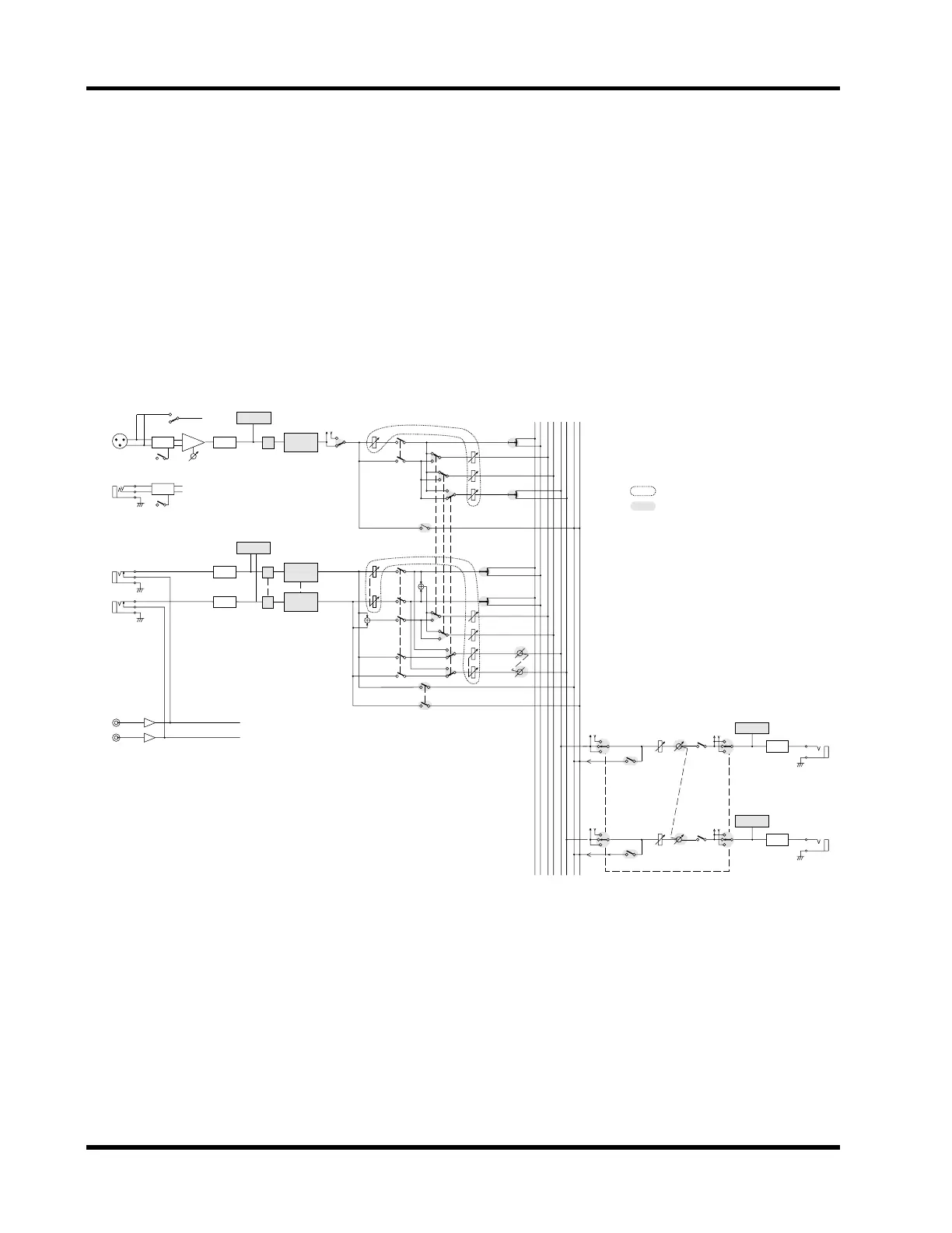
SEND3-4 Block Diagram
This block diagram shows what happens when SEND3 and SEND4
are configured as a stereo pair: Input channel SEND3 and SEND4
controls become a single control, and a SEND3-4 pan control
appears. On the stereo input channel, a SEND3-4 balance control
appears. The left signal feeds SEND3 and the right signal feeds
SEND4. Levels are controlled together. On the SEND3-4 outputs, a
SEND3-4 output balance control appears. See “SEND3 and SEND4”
on page 45 for more details.
SEND3
+4dB
(UNBAL)
20dB
ON
DA
METER
METER
GAIN
HAPAD
CH1–8
INPUT
(BAL)
PHANTOM MASTER (+48V)
ON
OFF
ON
2TR IN
–10dB
(UNBAL)
R
L
R
L
METER
ø
3BAND
PEQ
COMP
AD
ø
3BAND
PEQ
AD
ø
3BAND
PEQ
AD
COMP
COMP
ST
L R 1 2 3 4 L R
Multifunction faders and switches
LCD functions
ST IN
+4dB
(UNBAL)
20dB
PAD
CH9–16
SEND CUE
Same as
CH 1–8
SEND4
+4dB
(UNBAL)
ON
DA
METER
COMP
COMP
SEND3-4
BALANCE
CH FADER
SEND1
SEND2
SEND3-4
SEND3-4
PAN
CUE
PRE/POST
ST IN FADER
SEND1
SEND2
SEND3-4
DUAL
PAN
CUE
CUE
SEND3
FADER
SEND4
FADER
CUE
PAN
SEND3-4
BALANCE
ON