Pair Block Diagram
59
ProMix 01 User’s Guide
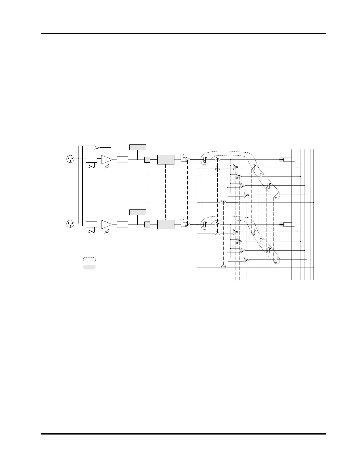
Pair Block Diagram
This block diagram shows what happens when adjacent input chan-
nels are paired: PHASE, EQ, COMP patch, faders, ON/OFF, CUE,
SEND1, SEND2, SEND3, and SEND4 are linked for simultaneous
control. The dotted lines show which channel functions are linked.
The send PRE/POST switches are always linked.
20dB GAIN
HAPAD
PHANTOM MASTER (+48V)
ON
OFF
ON
ø
3BAND
PEQ
COMP
AD
ST
L R 1 2 3 4 L R
SEND CUE
CH FADER
SEND1
SEND2
SEND3
SEND4
PAN
PRE/POST
20dB GAIN
HAPAD
ON
METER
ø
3BAND
PEQ
COMP
AD
PAN
PRE/POST
Phantom
power feed
CUE
CH FADER
Multifunction faders and switches
LCD functions
ODD
Channel
EVEN
Channel
METER
CUE
SEND1
SEND2
SEND3
SEND4