Periodic maintenance and adjustment
111
RST90PGT
11. Connect the negative battery lead by in-
stalling the bolt.
12. Install the battery cover, and then hook
the battery band onto the holder.
13. Install the air filter case by reversing the
removal steps 4–7.
14. Install the headlight unit, making sure to
fit the slots on its bottom onto the projec-
tions on its stay.
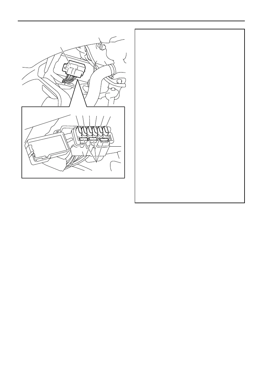
1. Fuse box
2. “IGN” (ignition) fuse
3. “S/H” (helmet shield heater jack) fuse
4. “HEAD” (headlight) fuse
5. “SIG” (signaling system) fuse
6. “DC” (auxiliary DC jack) fuse
7. Spare fuse
Specified fuses:
Main fuse:
40.0 A
EPS fuse:
30.0 A
Fuel injection system fuse:
10.0 A
Ignition fuse:
15.0 A
Radiator fan fuse:
RS90P 5.0 A
RS90PLT 5.0 A
Headlight fuse:
20.0 A
Signaling system fuse:
RS90P 3.0 A
RS90PLT 3.0 A
RST90PGT 7.5 A
Auxiliary DC jack fuse:
3.0 A
Helmet shield heater jack fuse:
3.0 A
Spare fuses:
RS90P / RS90PLT 20.0 A, 15.0 A,
10.0 A, 5.0 A, 3.0 A
RST90PGT 20.0 A, 15.0 A, 10.0 A,
7.5 A, 3.0 A
U8HV11E0.book Page 111 Monday, April 23, 2012 9:34 AM