•
Primary
Sheaves,
Secondary Sheaves, Drive-Belt,
DRIVE
TRAIN
&
CHASSIS
MAIN'FENANCE
-
Primary
Sheave and Secondary Sheave Alignement
CHAPTER
8.
DRIVE TRAIN AND CHASSIS MAINTENANCE
8-1
PRIMARY
SHEAVES
Very
I
ittle
maint
enance
of
th
e
primary
sheaves
is necessary,
how
ever,
periodi
c removal, checking and
lubri
cation
is
advi
sab
le. The
mati
ng
surfaces
of
the crankshaft and the
sliding sheave sho
uld
be
lubricated
w
it
h
molybdenum
d
is
ulf
ide grease.
Any
warpage of
either
the
primary
fixed
sh
eave
or
primary
sliding sheave m i
ght
indicate
improper
prima
ry
spri
ng
lens ion. The
four
count
er
weight
hooks
inside
the
pr
ima
ry
sl1eave cap shou
Id
be
periodically
l
ubri
cated
at
their
pivot
points
with
a grap
hite
spray
lub
ric
ant.
Caution:
Excessive amounts
of
lubricant
on the
primary
sheave
will
be
transferred
to
the
''V''
be
lt
and slippage may
occur
at engageme
nt
speed.
8-2
SECONDARY
SHEAVES
After
appro ximately
40
ho
urs r
idi
ng
time, sliding secondary
sheave
should be rernoved and the
sec
ondary
s
haft
greased.
Th
is
wi
ll keep the sheave
from
bind
ing L
IP
from
lack
of
lubrication.
8-3
DRIVE-BELT
Tension
of
the drive-belt
is
ad
justed
by
maintain
i
ng
a
pre-determined distance between the centers
of
the
primary
and
seco
ncl
a
ry
sh
ea
ve
s.
I l sl
10L
1id be 1
0.8''
(270
mm)
.
Ad
just
ment
is
made by
sh
if
ting the engine
afte
r loosening
the
four
moun
t ing bolts.
Note:
New belt
widt~
1
is
1.24''
(31
mm).
Replace
the
be
lt
it
is
worn
to
a
width
of
1.0
4''
(26
mm).
•
-97-
8-4
PRIMARY
SHEAVE
AND
SECONDARY
SHEAV.E
ALIGNMENT
•
The
two
sheave assemblies
must
be
parallel with one
another
for
the
drive-belt
to
obtain
maximum
grip and
minimum
wear.
Use
the special sheave gauge
that
comes
in
our
special
tool
kit.
•
Fig.
8-1
~
-
·--·
--~--~-·-
-
. . .
-·
""
. -
...
-..
..
.. .
- ~
~
•
•
•
•
•
J
•
...
•
•
I
. '
-~-~-
~'-'-------·~~.,-..--~
·
. -
-·c:..::
·
----
- - -·--
.....--.....
, -
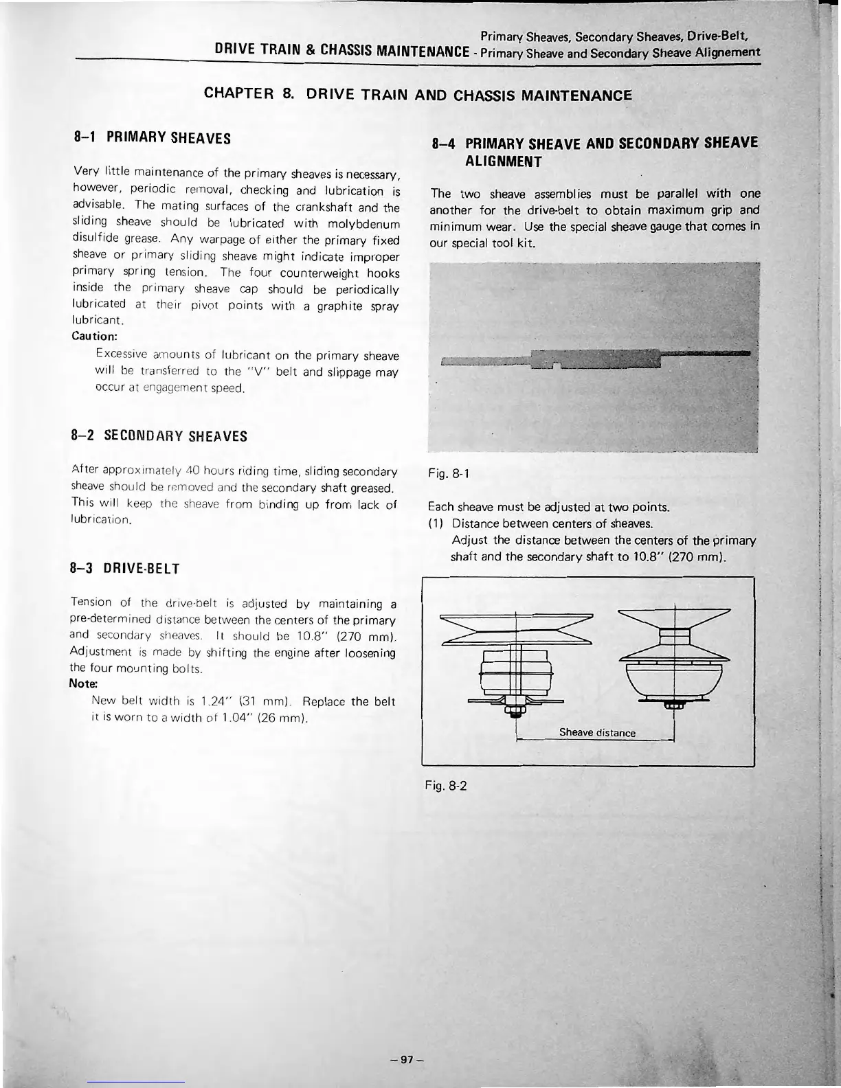
Each sheave
must
be adjusted
at
two
points.
( 1} Distance between centers
of
sheaves.
Adjust
the distance between
the
centers
of
the
primary
s
haft
and
the
secondary
shaft
to
10.8'' (270
mm).
Sheave distance
Fig. 8-2
•
•
•
•
•
•
•
•
•
t
•
•
•
•
•
.
'
•
.
•
•
•
.
I
I
I
'
I
•
'
'
!
I
•
I
•
'
•
•
•
.
•
' I
•
•
I
•
I
•
•
•
•
'
•
•
•
•
t
•
•
•
•
•
•
I
•
•
I
•
f
'
•
•
•
•
I
.
•
•
•
.
•










 To Next Page