ENGINE
MAINTENANCE
-
Top
End
Maintenance
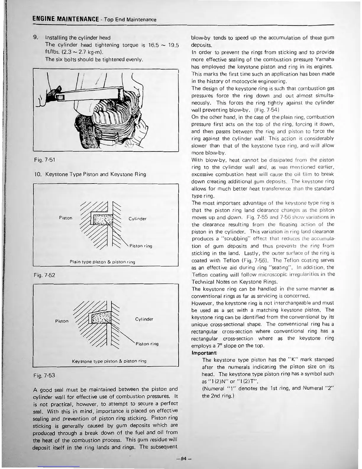
9.
Installing
the
cylinder
head
The
cylinder
head
tightening
to
rqu
e is 16.5
,....,
19.5
ft/lbs.
(2.3....,2.7 kg-m).
The
six
bolts
should be tightened e
ve
nl
y.
I
•
I
\
Fig. 7-51
10.
Keyston
e
Typ
e Piston and Keystone Ring
Pist
on
Cyli
nd
er
Pi
sto
n
ri
ng
Pl
ai
n
ty
pe
pist
on & p isto n r
in
g
Fig. 7-52
Piston
Cy
l i
nd
er
Pis
ton
rin
g
Keystone
typ
e p
iston
&
pist
o n
ring
Fig. 7-53
A
good
seal
must
be
maintained
between
the
pi
st
on
and
cylinder
wal
I
for
effective
use
of
combustion
pressures.
It
is
not
practical,
however,
to
attempt
to
secure a
perfect
seal.
With
this
in
mind,
importance
is placed
on
effe
c
tive
sealing and
prevention
of
piston
ring
sticking. Piston ring
sticking
is generally caused
by
gum
deposits
wh
ich are
produced
through
a break
down
of
the
fuel
and
oil
from
the
heat
of
the
combustion
process.
This
gum
residue
will
deposit
itself
in
the
ring
lands and rings.
The
subsequent
blow-
by
te
nd
s
to
sp
eed up the accum
ulati
on of
th
ese
g
um
depos
it
s.
In
order to preve
nt
the
rin
gs
from
sticking and
to
provide
more
effec
t ive
seal
ing of
the
combu
s
tion
pre
ssure
Yarnaha
h
as
empl
oye
d the keys
tone
piston and ri
ng
in its engin
es
.
T
hi
s r
na
rk
s
th
e
fi
rst t i
me
su
ct1
an
applic
at
ion
has
b
ee
n m
ad
e
in
th
e
hi
st
ory
of
mo
t
oc
yc
le engineerir
1g
.
Tt1e
design
of
the keys
to
ne ring is such
that
cornbustion
gas
pressu res f
orc
e the ring do
wn
a
nd
out
al
rn
ost s
imul
t
a-
neously. Th
is
for
ce
s
the
ring
ti
ght
ly
against the cylinder
wa
ll
pr
eventing bl
ow
-
by
. (Fig. 7-54)
On the
othe
r han
d,
in the c
as
e of the plain ring,
comb
ustion
pressure f irst acts
on
the
top of the ri
ng
, ·forcing it down,
and then
pa
sses
betw
ee
n
th
e ring and piston
to
for
ce
th
e
ri
ng
agai nst
tl
1e
cyli
nd
er wall:
This
ac
t
ion
is
co
nsiderably
sl
owe
r than that
of
the keystone ty
pe
ring, and w ill all
ow
mo
re blow-
by
.
Wi
th
blow-
by
, heat
ca
n n
ot
be dissipated
fr
om
the
piston
ring to the cy linder wall and,
as
was mentioned ear
li
er,
excessive combus
ti
on
he
at
w ill cause t
he
oil
film
to break
dow
n creat
in
g
ad
dit
io
nal gu m deposits. The keystone ring
allow
s
fo
r much be
tte
r heat
transf
erence tl
1a
n the standard
typ
e ring.
The
most
i
mp
ortant advanta
ge
of
t he keystone
type
ring
is
that the piston ring la
nd
clearan
ce
changes
as
the
piston
mo
v
es
up and
dow
n. Fig. 7-55 and 7-56 s
l1
ow
varia
li
o
ns
in
t
l1
e clearance
res
u
lt
ing from
the
floatin
g action
of
the
piston in the c
ylind
er. Th
is
va
r
iation
in ring land clearance
produ
ces
a
''
sc
rubbi
ng
''
eff
ec
t that redu
ces
lh
e accu mu l
a-
t ion of gum deposits and thus prevents lhe
rin
g
from
sticking in tl
1e
land. Lastl
y,
the outer surface
of
the ri
ng
is
c
oa
ted
V\
'ith
Tef
lon (Fi
g.
7-56). The T
eflon
coating
serves
as
an e
ff
ectiv
e aid dur i
ng
ring ''sea t
ing''
. In
addition,
t
he
Tefl
on
c
oat
i
ng
w
ill
fo
llow microscopic
ir
r
egLr
lariti
es
in the
Techn
ica
l Not
es
on Keystone Ri
ng
s.
The keystone ri
ng
can be handled in the
same
manner as
con
ve
nt
io
nal rings
as
far
as
servici
ng
is
concerned.
However,
th
e keystone ring is n
ot
interchangeab le and must
be u
se
d as a
se
t
wit
h a
matc
hin
g keystone piston. The
k
ey
st
one ring can be ident
if
i
ed
from
the conventi
on
al by its
uniqu
e c
ro
ss
-
sec
ti
onal shape. The convent ional ring h
as
a
rectangular cr
os
s-s
ec
t ion
wh
ere
con
ve
nti
onal ring
has
a
r
ec
tangular c
ro
ss-se
c
ti
on where
as
the keystone ri
ng
employ
s a 7° slope
on
the
to
p.
Important:
Th
e keystone
type
piston has the '' K''
ma
rk sta
mp
ed
aft
er
th
e
num
erals indicating
th
e
pi
ston
si
ze
on
it
s
head.
The
keys
ton
e
typ
e piston
rin
g
has
a sy
mb
ol such
as
'
'1
(2)N''
or
''
1 (2
)T'
'.
(Num
eral
''1
''
denot
es
th
e 1st ring, and
Num
eral
''
2''
the
2nd
ring.)
-
94-
•










 To Next Page