I
I
I
4. The piston pin-piston
fit
can
be checked
by
inserting
the piston
pin
into
the piston and checking the amount
of
re
sis
tan
ce
en
countered. The piston pin should
fit
int
o the piston
with
a snung,
thumb
press
fit.
Also check
the
needle bearings and needle bearing
cage
for
excessive wear,
or
overheating.
Fi
g.
7-46
5. T
he
piston rings are removed
from
the p
is
ton by
spreading them open
with
your
fi
ng
ers and lifting them
off
the piston. The piston ring
gap
c
an
be
c
he
cked by
placing the rings inside the
cylin
der bore horizontally.
The ring
gap
should
be
checked with a feeler
gauge
placed
int
o the opening between the ends of
th
e ring.
Maximum
gap
of
both upper and lower piston rings
sh
ould
not
ex
cee
d 0.006.....,
0.014''
(0.
15
.-
0.35
mm).
Fig.
7-4 7
6. Remove the carbon build-up
fr
om the p
is
ton
ring
grooves and repl
ace
the piston ring gap be aligned
with
the knock
pi
n in the ring groove
as
sh
ow
n in the
illustration. Th
is
is especially critical when installing
the
cy
lind
er over the piston.
I
I
Fig. 7-48
1'
I
.,.
•
ENGINE
MAINifEN"NCE
-
Top
End Maintenance
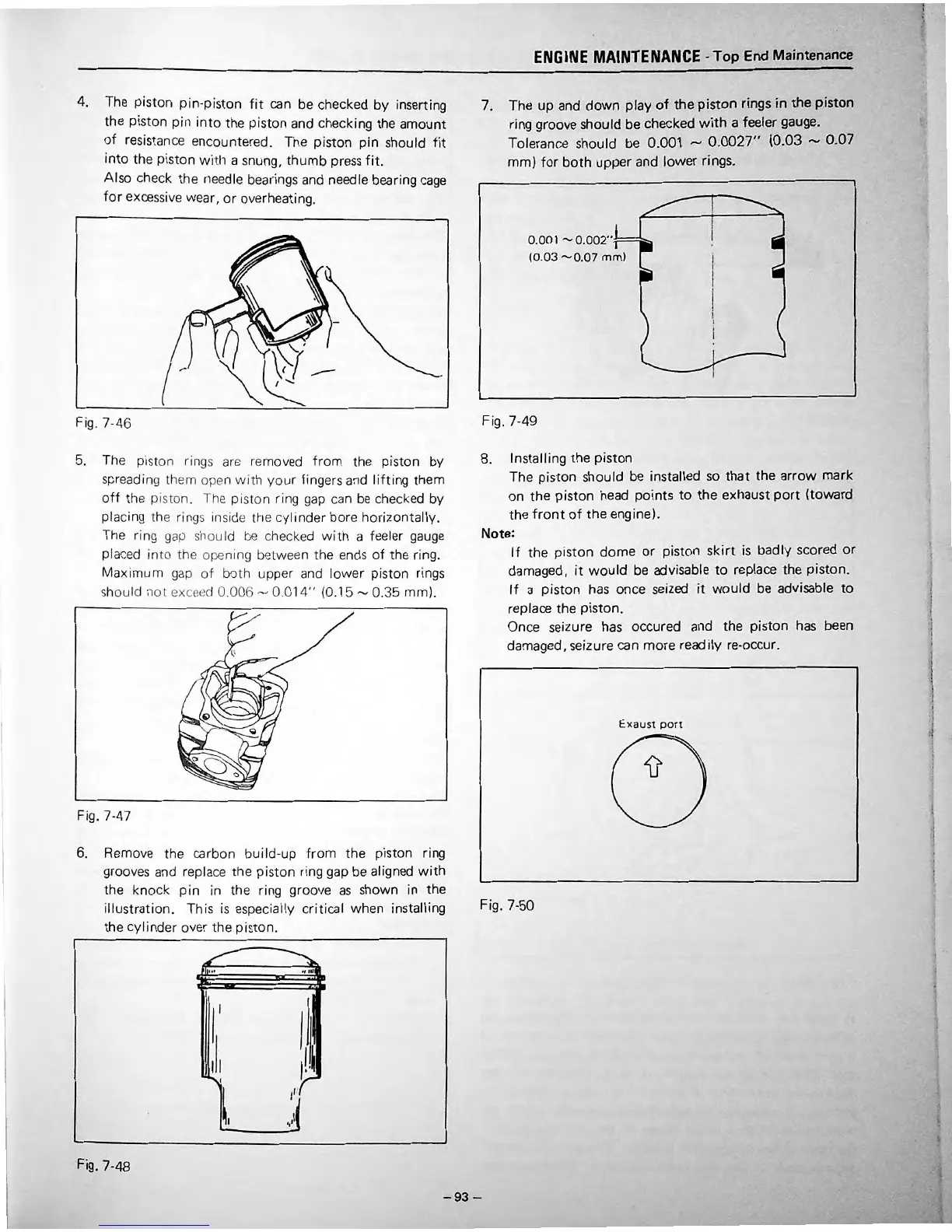
7. The
up
and
down
play
of
the
piston
rings
in
the
piston
ring groove should be checked
with
a feeler gauge.
Tolerance should be
0.001 _,
0.0027''
(0.03
_,
0.07
mm)
for
both
upper and lower rings.
0.001
--0.002'':!==
(0.
03
-0
.
07
mm)
Fig. 7-49
8. Installing
the
piston
•
I
I
I
I
The piston should be installed
so
that
the arrow mark
on
the
piston head
points
to
the exhaust
port
(toward
the
front
of
the
engine).
Note:
If
the piston
dome
or
piston
skirt
is
badly
sc
ored
or
damaged,
it
wou
Id
be
advisable
to
replace the piston.
If
a
pi
s
ton
has
once seized
it
would
be advisable
to
replace the piston.
On
ce
seizure has occured and the piston
has
been
damaged , seizure can
more
readily re-occur.
Exaust
port
Fig. 7
-5
0
-93-
•
•
•
•
•
•
•
•
•
1
I
•
•
f
I
I
•
•
l
I
•
I
I
l
I
I
I
'
I
J
•
•
I
I
i
•
I
I
I
•
•
•
I
•
•
•
 Loading...