•
•
ENGINE
-
Top
End
Reassembling Crankshaft Assembly
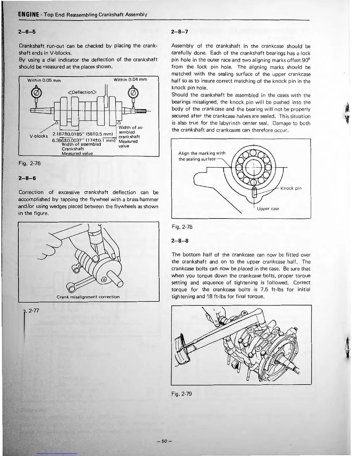
2-8-5
Crankshaft
run-out
can be checked
by
placing the crank-
shaft
ends
in
V-blocks.
By using a dial
indicator
the deflection
of
the crankshaft
should
be measured
at
the places shown.
Within
0.05
mm
Within
0.
04
mm
A
8
<Deflection>
~q_;
jell
..
e...
...
0
~
,_.
•
.
•
-
-
D.
D
Width
of
as
-
2.187±0.0185''
(56±0
.5
mm)
sembled
V-blocks
crankshaft
••
6.396±0.0037
( 174±0. l
mm)
Measured
Width
of
assembled value
Crankshaft
Measured value
Fig. 2-76
2-8-6
Correction
of
excessive crankshaft
deflection
can be
accomplished
by
tapping
the
flywheel
with
a brass hammer
and/or
using wedges placed between the flywheels
as
shown
in
the figure.
Crank misalignment
correction
. 2-77
•
•
2-8-7
Assembly
of
the crankshaft in
the
crankc
ase
should
be
carefully done. Each
of
the
cranks
haft
bearings has a
lo
ck
pin
hole in the
outer
race and
two
aligning marks
offset
90°
from
the
lock
pin
hole. The aligning marks should be
matched
with
the sealing surface
of
the
upp
er crankca
se
half
so
as
to
insure correct matching
of
the knock
pin
in
th
e
knock
pin
hole.
Should the crankshaft be
assembl
ed in the
cas
es
with
th
e
bearings misaligned, the
kno
ck
pin
wi
ll
be pushed
int
o
th
e
body
of
the crankcase and
th
e bearing
will
not be
prop
e
rly
secured
after
the crankcase halves are sealed. Th is
sitL1at
ion
is
also true
for
the la
byrinth
center
seal.
Damage to bo
th
the crankshaft and crankcases
ca
n
theref
ore occur.
Alig
n
th
e
marking
with
th
e
sea
ling
s
urfa
ce--
Fig. 2-78
2-8-8
K
nock
p
in
1
Upp
er case
The
bottom
half
of
the crankcase
can
now
be
fitted
ov
er
the crankshaft and on
to
the
upper crankcase half. The
crankcase
bolts
can
now
be
placed in the
case.
Be
sure
that
when
you
torque
dov.;n
the crankcase bolts, proper torque
setting and sequence
of
tightening is
follo
'Ned. Correct
torque
for
the crankcase
bolts
is
7
.5
ft-lbs
for
initial
tightening and
18
ft-lbs
for
final
torque.
Fig. 2-79
-50-
•
•
•
• •
,.
'•
• •
 Loading...