3-1-5
You
are
now
ready
to
remove
the
right
-hand secondary
s
haft
housing.
Use
a
hamm
er
and
soft
punch
to
tap the
right-hand housing back
out
of
the
cha
in
case.
Aft
er the housing is forced back,
you
will
have
to
s
lip
the
chain and drive sprocket
of
f the end
of
the s
haft
in order
to
com
plet
e
ly
remove
the
housing.
Once the housing has been tapped loose, then the housing
and secondary sh
eaves
can
be
removed
as
a
comp
lete
assembly. The gear can be separated
from
the chain and
placed
with
the assembly
just
removed. Care should
be
taken
to
avoid
dropping
the drive
sha
ft spacers and shim
into
the chain
case.
If a machine
ha
s secondary s
haft
shims
(some do
not)
they
should be reinstalled in
their
original
position
s.
/
~
\
\1
Fig. 3-5
3-
1-6
Th is ii lustr
at
ion shows the e
ntire
seco
ndary sheave
assem-
bly
removed and assembled on the bench.
Normally
this
s
hould
be
the
extent
of
disassembl
y,
but
if
a
problem
arises
in the
seco
ndary
sheaves
themselves, then additional break-
dov..in
wi
ll be required.
Th
is
will
be accomplished
by
first
removing the roll
pin
at
the
right-hand end
of
the shaft.
The
sp
ring
seat
will
slip
off
the end
of
the s
haft
once the
roll
pin
has
been removed. The spring
will
also slide
off
since it
is
held in place
only
by
the spring seat. This
would
complete the final disassemb!y
of
th
e secondary sheave
assembly .
Fig.
3-6
POWER
TRAIN
- Disc Brakes and Secondary Sheaves
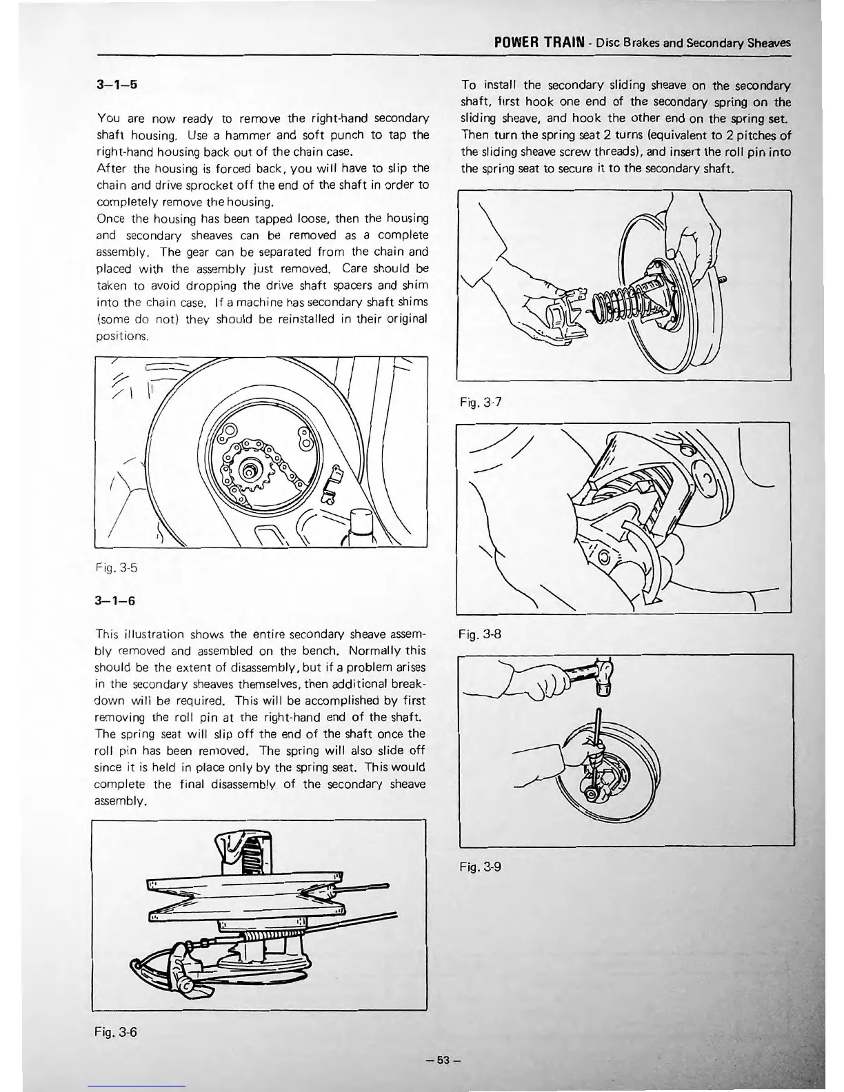
To
install the secondary sliding sheave on
the
secondary
shaft,
first
hook
one end
of
the
secondary spring
on
the
sliding sheave, and
hook
the other end
on
the spring set.
Then
turn
the
spring seat 2 turns (equivalent
to
2 pitches
of
the sliding
sheave
screw threads), and insert the
roll
pin
into
the spring
seat
to
secure
it
to
the secondary shaft.
Fig.3-7
Fig. 3-8
Fig. 3-9
-53-
 Loading...