r
__,
,
57
J.
i:
t
•
\ '
I
S·
I
) .
•
••
I '
' '•
i
..
•
I:. • .
r
i·
I • •
, I •
I
•
I
.
..
I I '
, . .
'
I
•
J • • •
•
I . :
..
.
l
'
I
.
'
•
'
.
•
I
•
ff
I
~
! :
I :
. .
I
•
•
•
••
' .
'
.
,
I
•
.
!
•
•
•
•
I
I
'
.
' .
•
I
I
•
•
,
•
•
,
•
'
•
•
.
f
•
!
• •
I •
I
I '
t:
I.
.
'
•
I
I
'
~
·
•
•
f.
•
'
l.
•
•
.
'
{;
I
l
•
r,
1,
II
I·
I'
I
I
I
i
I
I
•
I
•
I
'
•
'
'
I
I
I
I
•
I
•
•
il
f i
11
{1
\
•
f
~
•
..
•
'
•
l
• •
'
~
'
l}
·1
'·
t:
, .
".
•
I
. ,
I
•
I
'
'
I
•
•
•
~
i
' I I
~·
If
'
f'
J.
a'
l l •
•
• •
I
'
1
'
•
~
j
•
I
•
-
·-
·-
--
..
.
•
_
,.,__
_
'.E
C
.,
•---
Z $ =
- .
.._.__
,.,.
"' -
-
....
-
..
.
...
..
ENGINE
MAINfENANCE
-Carburetion and Fuel System
pump
driv
ing chamber, thus vibrating
th
e fuel pu
mp
diaphragm.
As
a result, the fuel
is
dr
a
wn
from
the fuel
tank
,
through
the
fu
el pipe and inlet check valve,
into
th
e
fuel
pump
chamber.
Th
en,
th
e
fu
el co
ntinu
es
to
fl
ow
through
the
outlet
check valve and inlet co
ntrol
va
l
ve
i
nt
o
the regulator chamber .
When
the
fuel
flows
int
o
th
e
re
g
ulat
or
cha
mb
er,
th
e main
diaphragm is given a do
wnward
f
or
c
e,
and at
th
e
same
time,
the
diaphragm c
ontrol
lever is moved d
ow
n at
th
e one end
and moved
up
at
th
e o
the
r end.
Thi
s c
au
ses
t
he
inlet
control
valv
e (n
ee
dle)
to
mo
ve
up
to
its closed position and
stops
th
e
flow
of
fu
el
int
o
th
e
re
gu
la
to
r chamber.
As
the
fuel lev
el
low
er
es
,
th
e pre
ss
ur
e
aga
in
st
th
e
ma
in
diaphr
agm
de
cre
as
es
and the main diap
hra
gm
sp
ring over-
c
om
es
the
for
ce of
the
inlet tension s
pr
ing,
thu
s pushi
ng
up
the
inlet
co
ntr
ol lever
at
th
e one end. Th
is
ca
u
ses
the inlet
c
ontrol
lever to
mov
e d
own
at the other end ,
an
d al lows the
inlet
c
ont
r
ol
valve
to
mo
ve do
wn.
At
th
is movement , the
fuel begins
to
flow
in.
Th
is i
s,
as
the fuel lever in the
regulator
chamber lower
s,
th
e inl
et
con
tr
ol
va
l
ve
open
s.
On
the
c
ontrary,
as
th
e
fu
el l
eve
l r
ises,
the inlet
control
va
l
ve
begins
to
c
lo
se
.
In
this
way
,
th
e balan
ce
between the main
di
a
phr
agm
sp
ring
tension and
th
e inl
et
tension spring
te
nsion
ma
int
ai
ns
th
e
fuel
level cons
tant
, a
nd
th
e
fu
el
is
fed
to
the engine.
At
l
ow
speed,
th
e
fu
el is
draw
n
int
o
th
e engi
ne
through the idle
discharge
port
alon
e .
With
1
/4
thro
tt
le
or
more, the
fu
el is
dr
awn
thr
ough t
he
main
di
scharge
port
a
nd
full
y atomized in the
pri
mary
venturi
, being supplied to
th
e
eng
in
e.
The
fuel
is
co
ntrolled
by the
sl
ow adjus
tin
g
sc
rew at l
ow
speed and
by
the
main
adj
ust
i
ng
scr
ew
at high sp
eed
at
a
proper
rate
according to
fu
el cons
umpt
ion in the
en
gi
ne
.
7-2-2
Carburetor
Setting
All
carburetors
are s
ubj
ect to
strict
t
es
ti
ng before ship-
ment.
Therefore,
no
attempt
to
touch
the
adjusted po
int
s
should
be made
unne
cessarily,
otherw
ise
th
e pe
rform
an
ce
of
the
carburetor
will
be impaired.
If
the
ca
rbur
etor
is
checked, cleaned,
or
disassembled f or replaceme
nt
of
part
s,
or
used
under
special
atmo
sphe
ri
c co
nditi
on
s,
or at alt i
tu
d
e,
the
following
procedur
es
mu
st be fo
ll
owed w
ith
special
ca
re
for
readjustment
.
The
adjustm
e
nt
point
s are t
hr
ee
pl
aces
as
follows:
1.
Slow
adjusting screw c
ontrolling
the
mixtur
e at idli
ng
speed.
2.
Throttle
. stop screw (idle speed screw) c
ontrolling
th
e
idling
speed.
3.
Main
adjusting screw
control
I ing the air-fuel mix
tur
e
while
the
throttle
shutter
is
past 1
/4
throttle.
•
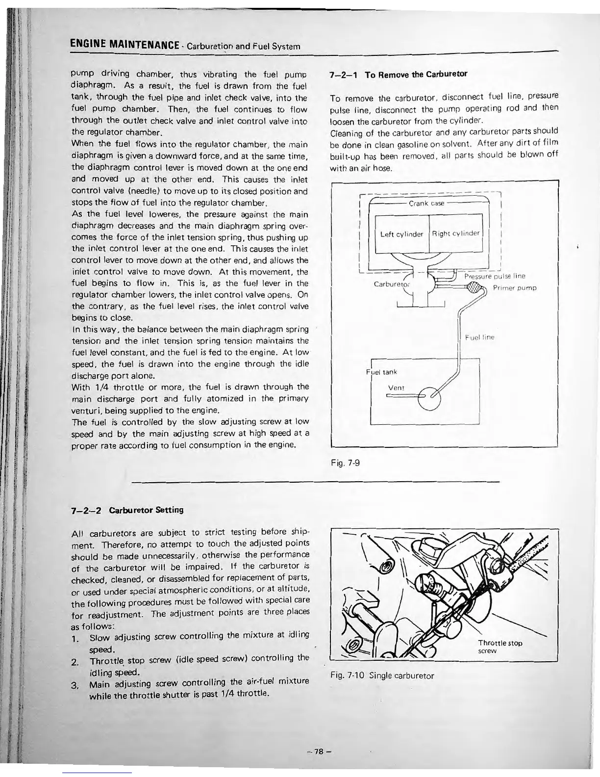
7-2-1
To
Remove the Carburetor
To rern o
ve
t
he
ca
rburetor, disconnect
fLiel
lin
e,
pressu
re
pulse lin
e,
disconnect the pump o
pe
rating rod and then
l
oose
n the
ca
rbure
to
r from tl1e cylinder.
Cleaning of the carburetor and any
ca
rburetor parts sh
ou
ld
be done in cl
ean
gas
oline on solve
nt
.
After
any di
rt
of
film
bu
ilt
-up h
as
been
removed, all parts should be blown
off
with an air hos
e.
--
---
-,
,--
-
-----
--
I
I
I
I
I
I
I
I
1---
--
Crank case
-----\
Le
ft
cylinde
r R
ight
cy
lind
er
I
I
I
l
L---
--
--
-
-~
-.....
Pr
ess
ure
pulse Ii ne
Jr:==
==
~~
Primer
pump
Ca
r
bur
etor
Fuel
tank
Vent
Fig. 7-9
-r
,,--_
'
Fig. 7-10 Single
ca
rburetor
•
•
Fu
el
line
T hrot
tle
sto
p
screw
-78-
.
•
'
•
'
•
'
•
•
•
•
•
•
I
I
t
 Loading...