2
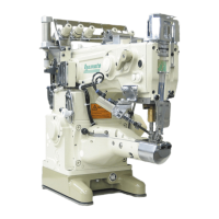
VE2700-8
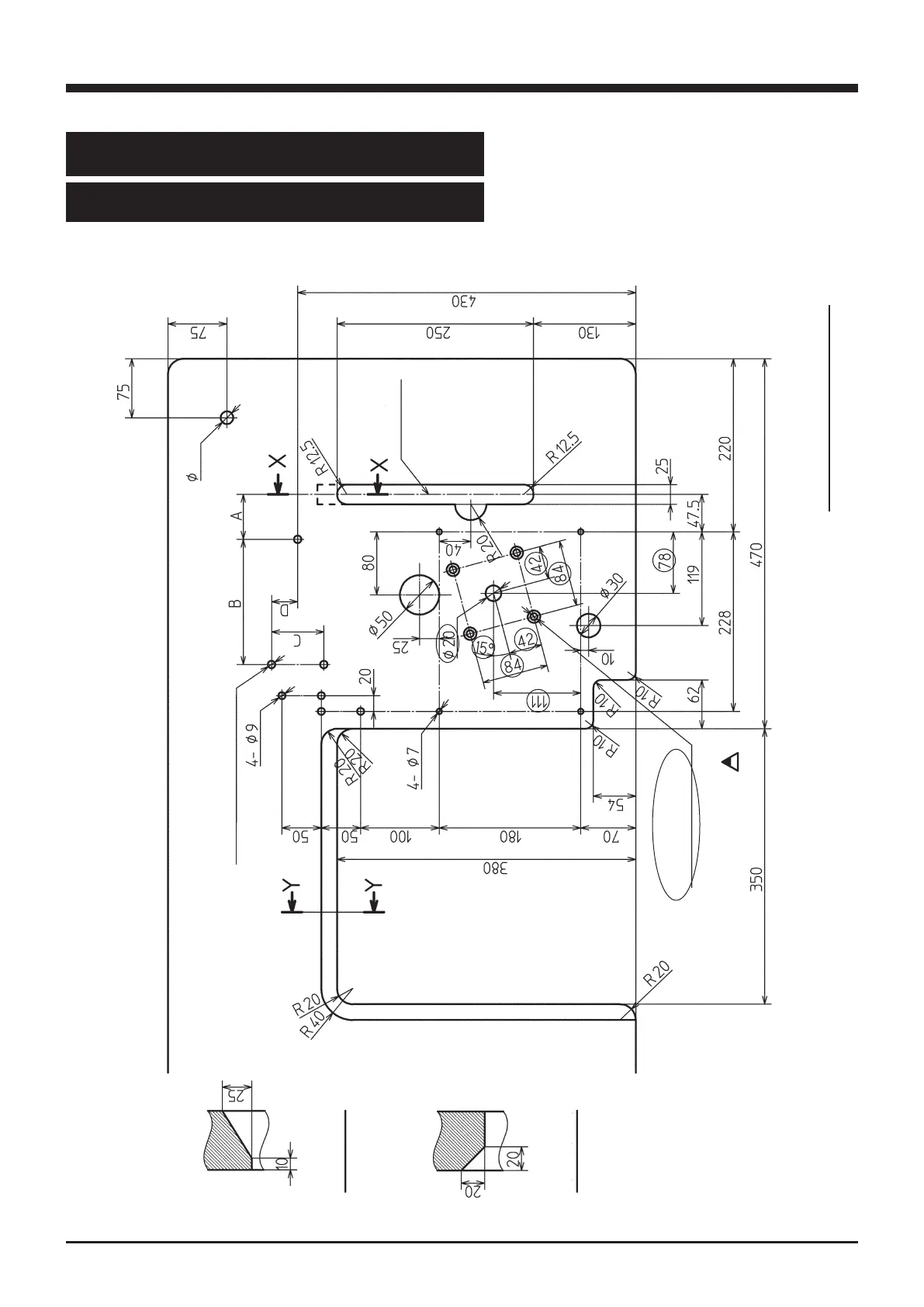
2. Installation
2.1 Table cutting diagram
2.1.1 Table top type (Type A: standard)
17
The circled dimensions are required only for models with UT device.
Fig. 2-1
Refer to the instruction manual of the motor
for dimensions A, B, C, and D.
Section X-X
Section Y-Y
Center of pulley
Operator
3-Φ9.5
(Installing hole for motor)
Table dimensions: 1200×595×50
4-Φ9 Φ16 countersunk
hole depth 16
 Loading...