28
B. Metric threads
Same as above when a Metric Screw is installed.
To provide for the various pitches of metric threads, several gears
having different numbers of teeth are mounted on the lower end of the
shaft. The
vertical position of the thread dial indicator is changed as required so
that the correct gear for the pitch of the thread to be cut wills mesh with
the leadscrew.
Each graduation on the dial is marked with a letter, which indicates
the points at which the half nuts may be engaged for certain threads. A
diagram is supplied with the thread dial to show which gear and
graduations must be used for each pitch of metric screw thread.
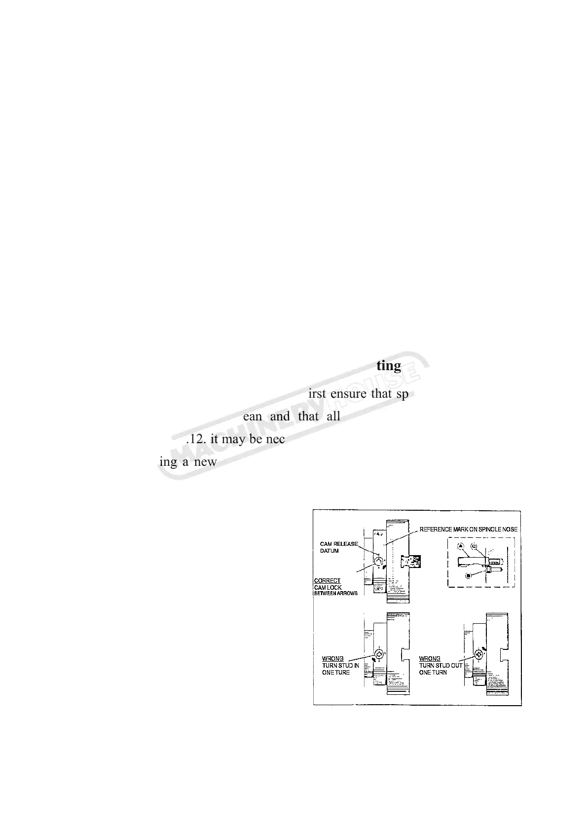
14. Chucks and Chucks Mounting
When fitting chucks or faceplates, first ensure that spindle and chuck
tapers are scrupulously clean and that all cams lock in the correct
positions; see Fig.12. it may be necessary to re-set the cam lock studs (A)
when mounting a new chuck. To do this, remove the cap-head locking
screws (B) and set each stud so that the scribed ring (C) is flush with the
rear face of the chuck-with the slot
lining up with the locking screw hole.
See Fig.13.
Now, mount the chuck or
faceplate on the spindle nose and
tighten the three cams in turn.
When fully tightened, the cam
lock line on each cam should be
between the two V marks on the
spindle nose. If any of the cams
do not tighten fully within these limit marks, remove the chuck or
Fig.13
Instructions Manual for CL-38 (L190)