SYSTEM DIAGRAMS
YM Series Operation Manual 91
12/05
Unit: mm (in.) 1 – 7.8 x t4.5 Rubber Hose
2 – Check Valve
3 – 7.8 x t4.5 Rubber Hose
4 – 7.8 x t4.5 Rubber Hose
5–Overflow
6 – Fuel Inlet
7 – 7.8 x t4.5 Rubber Hose
8 – 5 x t4.5 Rubber Hose
9 – 7.8 x t4.5 Rubber Hose
10 – Fuel Feel Pump
11 – Fuel Injection Pump
12 – 4.76 x t0.7 Steel Pipe
13 – Engine Oil Filter (cartridge
type)
14 – 4.76 x t0.7 Steel Pipe
15 – Fuel High-Pressure Pipe
16 – Fuel Injection Nozzle
17 – Oil Pressure Switch
18 – Mixing Elbow
19 – 17 x 14 Rubber Hose
20–Heat Exchanger
21 – Engine Oil Inlet Filter
22 – Main Bearing
23 – Seawater Inlet
24 – 17 x t4 Rubber Hose
25 – Seawater Pump
26 – 28 x t4 Rubber Hose
27 – 28 x t4 Rubber Hose
28 – Hot Water Connection Outlet
(R3/8)
29 – Thermostat
30–Coolant Pump
31 – Hot Water Connection Inlet
(R3/8)
32 – Coolant Temperature Switch
33 – Engine Oil Pump
34 – Pressure Control Valve
35 – Diesel Fuel
36 – To Oil Pan
37 – To Camshaft
38 – From Cylinder Head
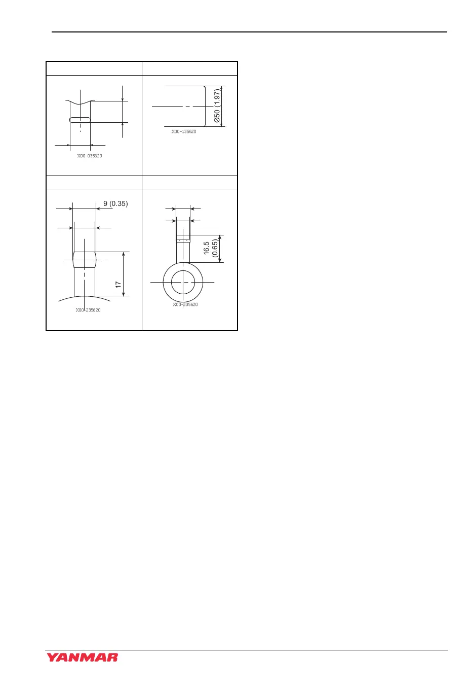
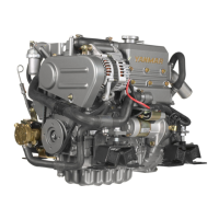
Detail of part A Detail of part B
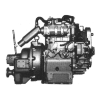
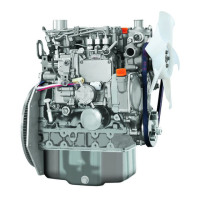
Detail of part C Detail of part D
Ø17
(0.67)
18
(0.71)
026530-00X
Ø8 (0.31)
Ø9 (0.35)
17 (0.67)
026532-00X
Ø8.5 (0.33)
Ø8 (0.31)
16.5
(0.65)
026533-00X
YM OPM_EN.book 91 ページ 2013年6月7日 金曜日 午前11時11分