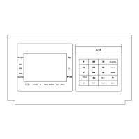
X K 3 1 9 0 –A23p
(3)
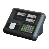
2. Load cell and weighing indicator connection :
A23p adopts 5 pin plug connect with sensor, and definition are as follows:
Foot
position
definition
1 Excitation voltage +
(E+)
2 Excitation voltage -
(E-)
3
Signal+(S+)
4
Signal-(S-)
5
Shielding wire(SH)
(
picture 2-2-1)
▲ !warning::Weighing indicator power supply must be cut off when install the
load cell and wire connecting must be correct and reliable.
▲ !warning :To ensure the system is working fine , please fix the plug with screw
to the indicator after the signal source wiring, the user can not insert and pull out
plug at discretion, and it is forbidden while the indicator is on .
▲ !Signal source and weighing indicator are all static electricity sensitivity
equipment,so user must adopt anti-static electricity when weighing indicator
works. To avoid the damage of the signal source and weighing indicator by
lighting strike and insure the operator's safety and correlative equipment working
well in the thunder storm season, the user must adopts credibility measures to
avoid lighting strike.
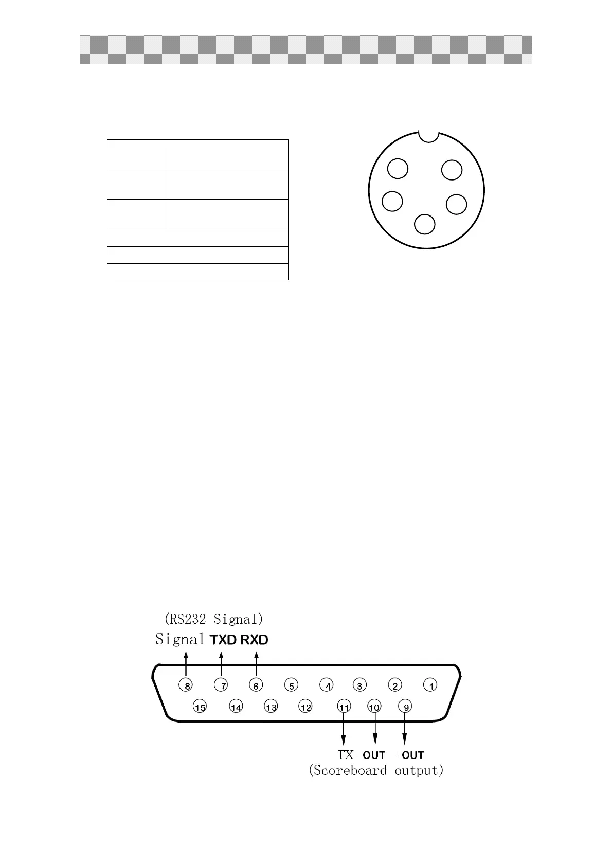
3. Communication interface definition:
Communication interface definition is as follows:
RS232 definitions:pin 6 is RXD,pin 7 is TXD,pin 8 is GND. scoreboard current loop
definition: pin 9 is current loop+,pin 10 is current loop-.
Scoreboard RS232 definition: pin 11 is used for connect scoreboard with RS232 connection
method
1
2
3
4
5
E+
E-
S+
S-
SH
Back of connector
 Loading...