VAN-V17001E<1>, Replacing A1000 crane with CR700
13/44
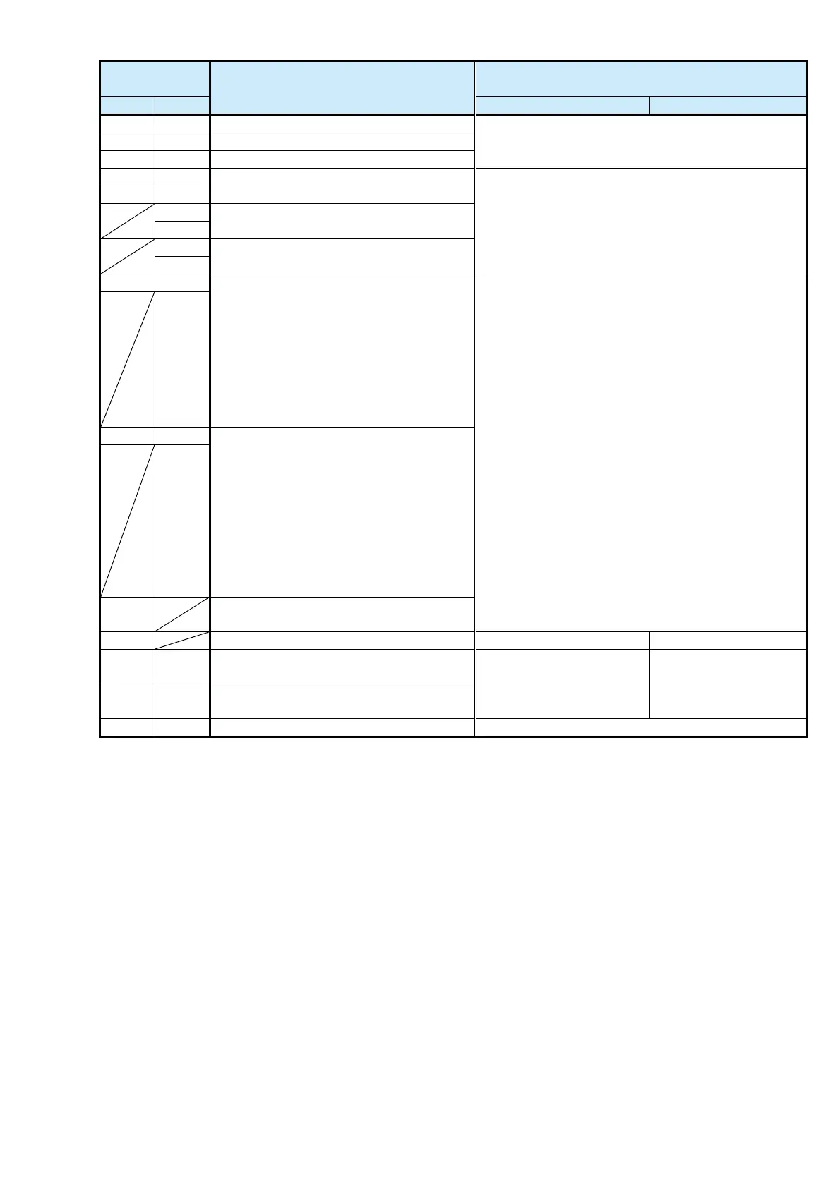
Control circuit
terminals
Name
Signal Level
A1000 CR700 A1000 CR700
MA MA 12RXWSXW)DXOW
Fault relay output
30 Vdc 10 mA - 1A
250 Vac 10 mA - 1A
MB MB 1&RXWSXW)DXOW
MC MC )DXOWRXWSXWFRPPRQ
M1 M1
Multi-function digital output (Brake Release
Command)
Multi-function digital output
30 Vdc 10 mA - 1A
250 Vac 10 mA - 1A
M2 M2
M3
Multi-function digital output (During run)
M4
M5
Multi-function digital output (Frequency
(Speed) Agree 1)
M6
P1 P1 Photocoupler output 1 (Zero speed)
Note: Default function differs between A1000
and CR700.
A1000: Zero Speed Control
CR700: Drive Ready
To change the function assigned to the
terminal in CR700 to Zero Speed Control,
change the parameter setting of CR700 so
that H2-04 = 1 (default setting is H2-04 = 6).
Multi-function photocoupler output
+48 Vdc 2 - 50 mA
C1
*3
P2 P2 Photocoupler output 2 (Speed agree 1)
Note: Default function differs between A1000
and CR700.
A1000: Speed Agree 1
CR700: Minor Fault
To change the function assigned to the
terminal in CR700 to Speed Agree 1,
change the parameter setting of CR700 so
that H2-05 = 2 (default setting is H2-05 =
10).
C2
*3
PC
*3
Photocoupler output common
MP Pulse train output (Output frequency) N+]Nȍ max. -
FM FM
Analog monitor output 1
(Output frequency)
-10 - +10 Vdc
(max. current 2 mA)
Resolution: 1/1000
-10 - +10 Vdc
(max. current 2 mA)
AM AM
Analog monitor output 2
(Output current)
AC AC
Monitor common
0 V
Terminal connections and drive settings
*1. Use the connection diagram on the following page when transferring the SC terminal wiring from A1000
to CR700.
*2. Transfer wiring from the DM+ and DM- terminals on A1000 to terminals M1 and M2 or to M3 and M4 on
CR700.
Or, transfer wiring to the P1 and C1 terminals, or to the P2 and C2 terminals on CR700.
- Set H2-01 = 51 when using the M1 and M2 terminals.
- Set H2-02 = 51 when using the M3 and M4 terminals.
- Set H2-03 = 51 when using the P1 and C1 terminals.
- Set H2-04 = 51 when using the P2 and C2 terminals.
*3. Transfer wiring from terminal PC on A1000 to either terminal C1 or C2 on CR700.

 Loading...


