VAN-V17001E<1>, Replacing A1000 crane with CR700
28/44
Control Circuit Terminal Sizes and Wire Gauge
Power
supply
Model Capacity Terminal Symbol
Ter m ina l
Screw
Tightening
Tor q u e
(N•m)
Applicable
Gauge
(mm
2
)
Recommended
Gauge
(mm
2
)
200 V
class
400 V
class
A1000
All
capacit
ies
FM, AC, AM, P1, P2, PC,
SC, A1, A2, A3, +V, -V,
S1, S2, S3, S4, S5, S6, S7, S8,
MA, MB, MC, M1, M2
M3.5 0.8 - 1.0 0.5 - 2.0 0.75
MP, RP, R+, R-, S+, S-, IG
DM+, DM-, H1, H2, HC
M2
Phoenix type
0.22 - 0.25
Stranded
wire
0.25 - 1.0
Solid wire
0.25 - 1.5
0.75
E(G) M3.5 0.8 - 1.0 0.5 - 2.0 1.25
200 V
class
400 V
class
CR700
All
capacit
ies
FM, AC, AM, P1, C1, P2, C2,
SN, SC, SP, A1, A2, A3, +V, -V,
S1, S2, S3, S4, S5, S6, S7,
S8,S9,S10,
MA, MB, MC, M1, M2, M3, M4,
MP, RP, D+, D-, H1, H2, HC,
PS, E(G)
M3
Phoenix type
0.5 - 0.6
Stranded
wire
0.2 - 1.0
Solid wire
0.2 - 1.5
0.75
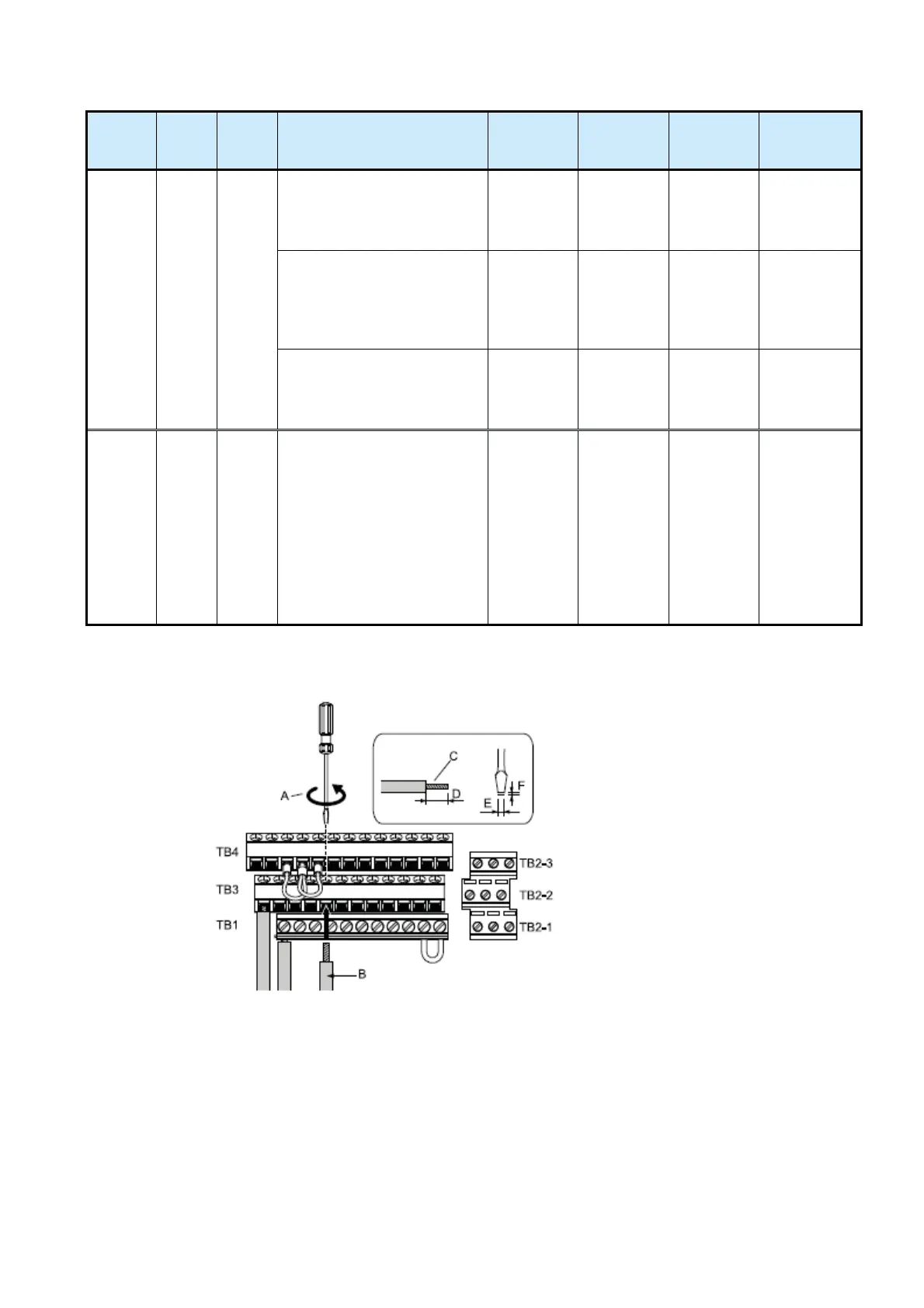
Terminal Board Wiring Guide
A: Loosen the screws to insert the wire.
B: Single wire or stranded wire
C: Avoid fraying wire strands when stripping insulation from wire.
D: When crimp ferrules are not used, remove approximately 5.5 mm of the covering at the tip.
E: Blade width of 2.5 mm or less
F: Blade depth of 0.4 mm or less

 Loading...


