5 Installation Procedure
16 YASK AWA E LEC TRI C TOBP C730600 37B 1000-Series Option PG-X3 Installation Manual
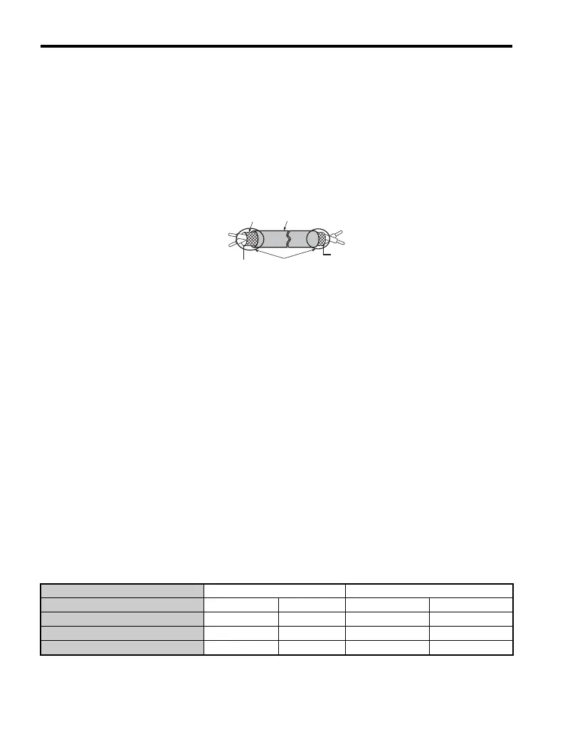
4. Prepare wire ends as shown in Figure 6. Refer to Wire Gauges and Tightening
Torques on page 20 to confirm that the proper tightening torque is applied to each
terminal. Take particular precaution to ensure that each wire is properly connected
and wire insulation is not accidentally pinched into electrical terminals.
WARNING! Fire Hazard. Tighten terminal screws to the specified tightening torque. Loose electrical
connections could result in death or serious injury by fire due to overheating. Tightening screws beyond the
specified tightening torque may cause erroneous operation, damage the terminal block, or cause a fire.
NOTICE: Heat shrink tubing or electrical tape may be required to ensure that cable shielding does not
contact other wiring. Insufficient insulation may cause a short circuit that can damage the option or drive.
Figure 6
Figure 6 Preparing Ends of Shielded Cable
5. Wire the motor PG encoder to the terminal block on the option. Refer to Figure 8 for
wiring instructions.
Refer to Option Terminal Functions on page 21 for a detailed description of the
option board terminal functions.
Parameter Settings and Connections for Different Encoder Types
• Connecting a Single-Channel Encoder
When using a single-channel encoder in V/f with PG control mode, connect the
pulse output from the PG to the option and set drive parameter F1-21 to 0.
• Connecting a Two-Channel Encoder
When using a two-channel encoder, connect the A and B pulse outputs on the PG
to the option and set F1-21 to 1.
When using a two-channel encoder in Closed Loop Vector control mode, connect
pulse outputs A and B from the encoder to the corresponding terminals on the
option.
• Connecting a Two-Channel Encoder with Z Marker Pulse
When using a two-channel encoder with Z marker pulse, connect the A channel,
B channel, and Z pulse outputs to the corresponding terminals on the option.
Control Method V/f with PG Closed Loop Vector
No. of Encoders 1 CN5-C 2 CN5-B 1 CN5-C 2 CN5-B
Single Channel (A) F1-21 = 0 F1-37 = 0 N/A N/A
Two Channel (AB Quadrature) F1-21 = 1 F1-37 = 1 No setting required No setting required
Two Channel with Marker (ABZ) F1-21 = 1 F1-37 = 1 No setting required No setting required
Insulation
Shield sheath
Shield
PG option terminal
PG at motor
FE/SD
Ground Terminal
(Insulate with electrical tape
or shrink tubing)

 Loading...


