2 Spindle Orientation
YASKAWA TM.A1000SW.063 Spindle Orientation A1000 Custom Software Supplement 21
An Orient from Stop can also be performed when the 80h Orient Command is applied while the drive is at rest and the
drive is then issued a run command.
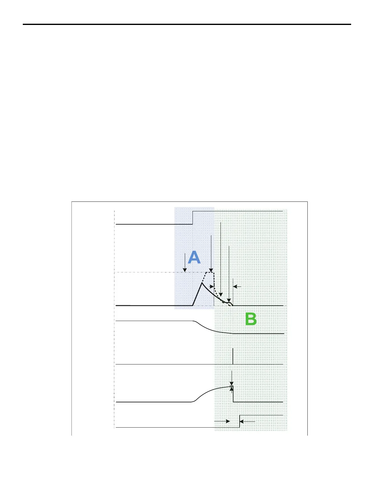
Area A: Acceleration
If the spindle is stopped at a position outside of the Orient Complete Detection Set Window and the Orient CMD FWD
(81h) is issued, the drive begins to run in the forward direction and accelerate to a speed determined by the product of the
real-time position error and the Positioning Proportional Gain P1-08. This speed is limited to a maximum of the P1-02
Creep Speed as demonstrated in Area A of Figure 6. If the spindle is to be oriented in the reverse direction, orient digital
input 82h (Orient CMD REV) should be used.
If the spindle position is within the Orient Complete Detection Set Window, the drive orients as described in Orientation
Set/Reset Window on page 28.
Area B: Deceleration and Control
Area B shows how the position regulator determines the frequency reference during orient. The Positioning Proportional
Gain parameter P1-08 adjusts the responsiveness of the position regulator. Unlike an Orient from run, the drive does not
look for the marker pulse when performing an Orient from Stop because the marker position has already been determined
(except during a power-up condition as described in Orient from Stop - Find Marker on page 22).
Note: Increasing Positioning Proportional Gain parameter P1-08 decreases the orient time when an orient from stop is performed (as
represented by the dashed line machine speed curve as represented in Figure 6 ). Increasing this gain may also cause overshoot, if
this happens, decrease P1-08 until the overshoot disappears. Raising the P1-02 Creep Speed decreases the orient time of an orient
from stop.
Figure 6
Figure 6 Orient Profile from Stop
Note: If an 81h Orient CMD FWD or 82h Orient CMD REV digital input is removed and reapplied while the Orient Complete output
ORTSetTime(P1-07)
OrientComplete
A/BPulseCount
(Equivalentto
ShaftAngle)
ZMarkerPulse
MachineSpeed
(Hz)
OrientCMDFWD
AccelTime
(C1-0X)
CreepSpeed
(P1-02)
ORTSetWindow
(P1-05)
(H1-0X=81h)
(H2-0X=40h)
CreepDistance
(P1-03)
ApproachSpeed
(P1-04)
PositionError
HighP1-08Gain
OrientationProfile
Position-Error×
P1-08Gain
BasedSpeed

 Loading...


