5. CONFIGURATION 4
5. 1 CONNECTION DIAGRAM
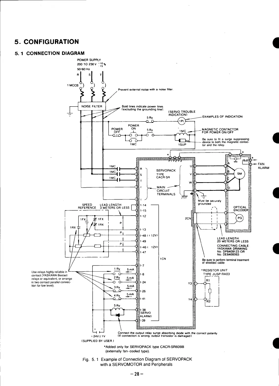
POWER SUPPLY
200 TO 230V +10%
-15
50160 Hz
1MCCB )
Prevent external noise with a noise filter.
S NOISE FILTER 1 _ Bold lines indicate power lines
f
(excluding the grounding line). (SERVO TROUBLE
-- _ INDICATION)
5 Ry _ EXAMPLES OF INDICATION
POWER
POWER ON 5 Ry MAGNETIC CONTACTOR
OFF --L_ __ _FOR POWER ON/OFF 4
---.C) I ____-_O O _ 1 Be .... to fit a surge suppressing
=_'_1-_- device to both the magnetic contac-
1MC 1SUP i tor and the relay.
g
1Me a I R "_ U _ ALARM
_ 1MC: / SERVOPACK
,t '_s / TYPE | v_
: 1MC| I [CACR-SR J _
• : 4
/ cIRcuIT I _
JTERMINALS \7._ _M_besecurely
SPEED LEAD LENGTH grounded
REFERENCE 3 METERS OR LESS ,/_.
2Ch I I
i
mPim
(_
LEAD LENGTH:
20 METERS OR LESS
P t ( CONNECTING CABLE: ,_
YASKAWA DRAWING
I
No, DP8409123 OR
No, DE8400093
1CN Be sure to perform terminal trearment
of shielded cable
1 Ry 5mA *RESISTOR UNIT
Use relays highly reliable in
contact(YASKAWABestact O TYPEJUSP-RA03
relays or equivalent, or arrange 2 R._.yy .5mA
intwocontactparallelconnec- Y3
tion for low level). 3 Ry 5mA
4 Ry 5_mA
I, Y4
5 Ry
Connect the output relay surge absorbing diode with the correct polarity
+ 24V _ 1V (If connection is wrong, output transistor is damaged). ..,.]
(I
(SUPPLIED BY USER)
*Added only for SERVOPACK type CACR-SR60BB
(externally fan-cooled type).
Fig. 5. 1 ExampleofConnectionDiagramofSERVOPACK
witha SERVOMOTORand Peripherals
-28-
 Loading...


