1 SWITCH .OPERATION
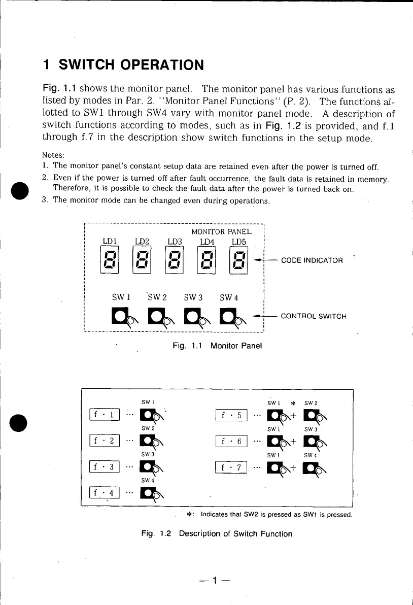
Fig. 1.1 shows the monitor panel. The monitor panel has various functions as
listed by modes in Par. 2. "Monitor Panel Functions" (P. 2). The functions al-
lotted to SW1 through SW4 vary with monitor panel mode. A description of
switch functions according to modes, such as in Fig. 1.2 is provided, and f. 1
through f.7 in the description show switch functions in the setup mode.
Notes:
1. The monitor panel's constant setup data are retained even after the power is turned off.
2. Even if the power is turned off after fault occurrence, the fault data is retained in memory.
Therefore, it is possible to check the fault data after the power" is turned back on.
3. The monitor mode carl be changed even during operations.
.................................................. 1
MONITOR PANEL
,,
LD1 LD2 LD3 LD4 LD5 . [
[ CODE INDICATOR
i
*
i
SW1 'SW2 SW3 sw 4 i
i
i
O T O.S ,TOH
.................................................. i
Fig. 1.1 Monitor Panel
SWI SWl $ SW2
_-_ • _o, _ ..._,,, _,
SW 2 SW I SW 3
_..._ _... _,, _
SW 3 SW 1 SW 4
_ ..._, F:_ ...D_,,_
SW 4
_ ..._,,
• : Indicatesthat SW2is pressedas SW1 is pressed.
Fig. 1.2 Description of Switch Function
 Loading...