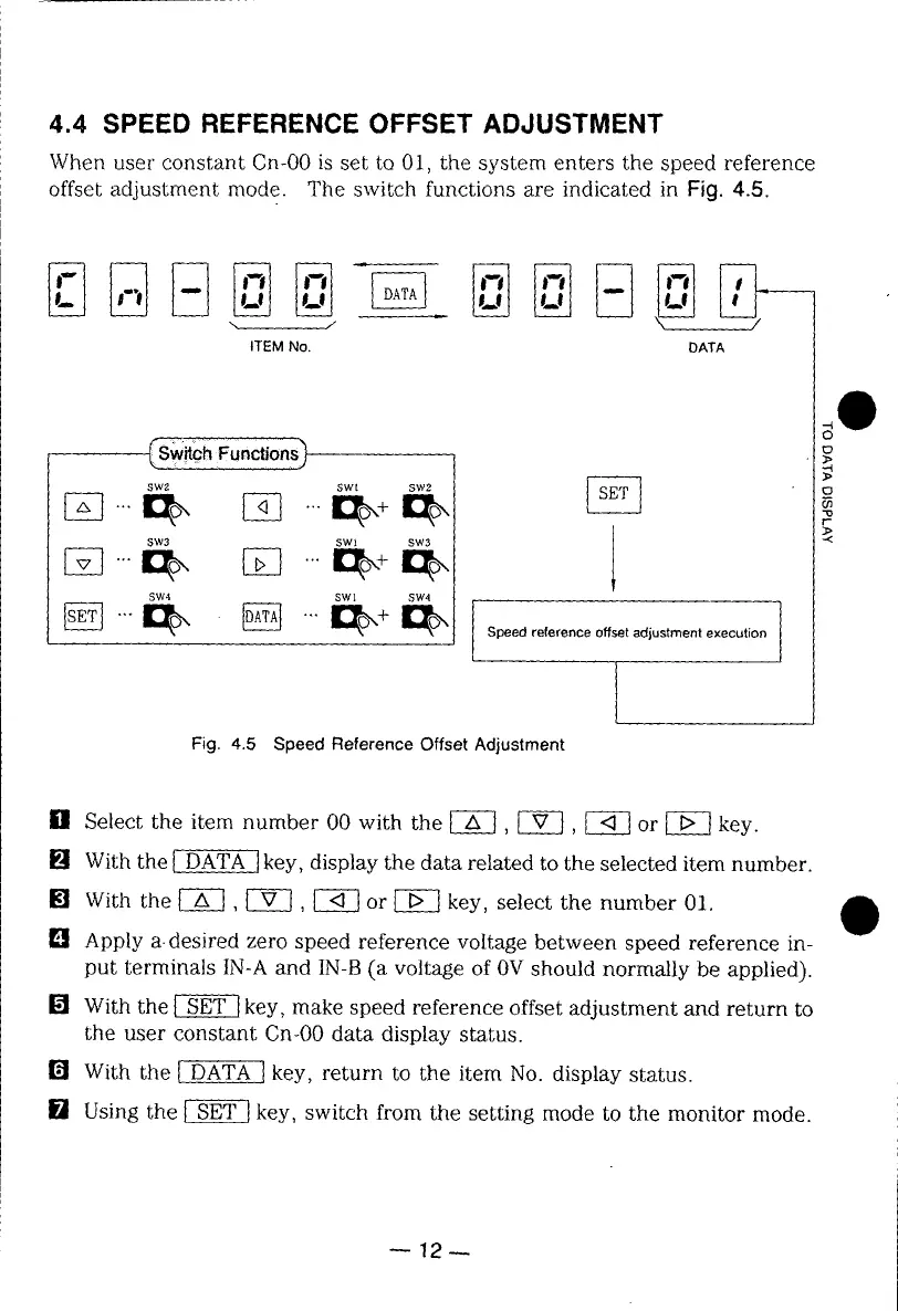
4.4 SPEED REFERENCE OFFSET ADJUSTMENT
When user constant Cn-O0 is set to 01, the system enters the speed reference
offset adjustment mode. The switch functions are indicated in Fig. 4.5.
ITEM No. DATA
O
F..ctio@
SW2 SWt SW2
SW3 SWI SW3 .5<
lob lab+lab
SW4 SWl SW4
Fig. 4.5 Speed Reference Offset Adjustment
[] Select the item number 00 with the [-_, _, _ or _-_ key.
[] With the _ key, display the data related to the selected item number.
[] With the [--_-], [7_, [_ or _ key, select the number 01.
[] Apply a-desired zero speed reference voltage between speed reference in-
put terminals IN-A and IN-B (a voltage of 0V should normally be applied).
[] With the _ key, make speed reference offset adjustment and return to
the user constant Cn-00 data display status.
With the l DATA I key, return to the item No. display status.
U Using the [-_ key, switch from the setting mode to the monitor mode.
--12--
 Loading...