4. SETTING MODE
In this mode, the following operations call be performed.
• User constant setup and monitor
• Jog operations from the monitor panel
• Speed reference offset adjustment
• Fault traceback data clearing
4.1 USER CONSTANT (DATA) SETUP AND MONITOR
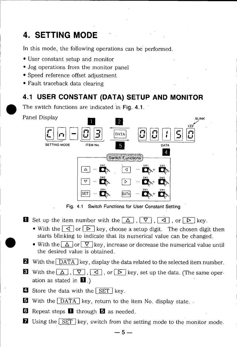
The switch functions are indicated in Fig. 4.1.
Panel Display [] [] ,,_,NK
"_T/.
SETTING MODE ITEM No. _/_ DATA
II
SWl sw2
SW4 SWI SW4
Fig. 4.1 SwitchFunctionsfor UserConstantSetting
[] Set up the item number with the [-A--] , IV-I, [_-], or _ key.
• With the _ or _ key, choose a setup digit. The chosen digit then
starts blinking to indicate that its numerical value can be changed.
• With the _ or _ key, increase or decrease the numerical value until
the desired value is obtained.
[] With the _ key, display the data related to the selected item number.
[] With the [_, [_, [-_, or _ key, set up the data. (The same oper-
ation as stated in [] .)
[] Store the data with the _ key.
[] With the [.)3ATA Ikey, return to the item No. display state..
[] Repeat steps [] through [] as needed.
[] Using the _ key, switch from the setting mode to the monitor mode.
5
 Loading...