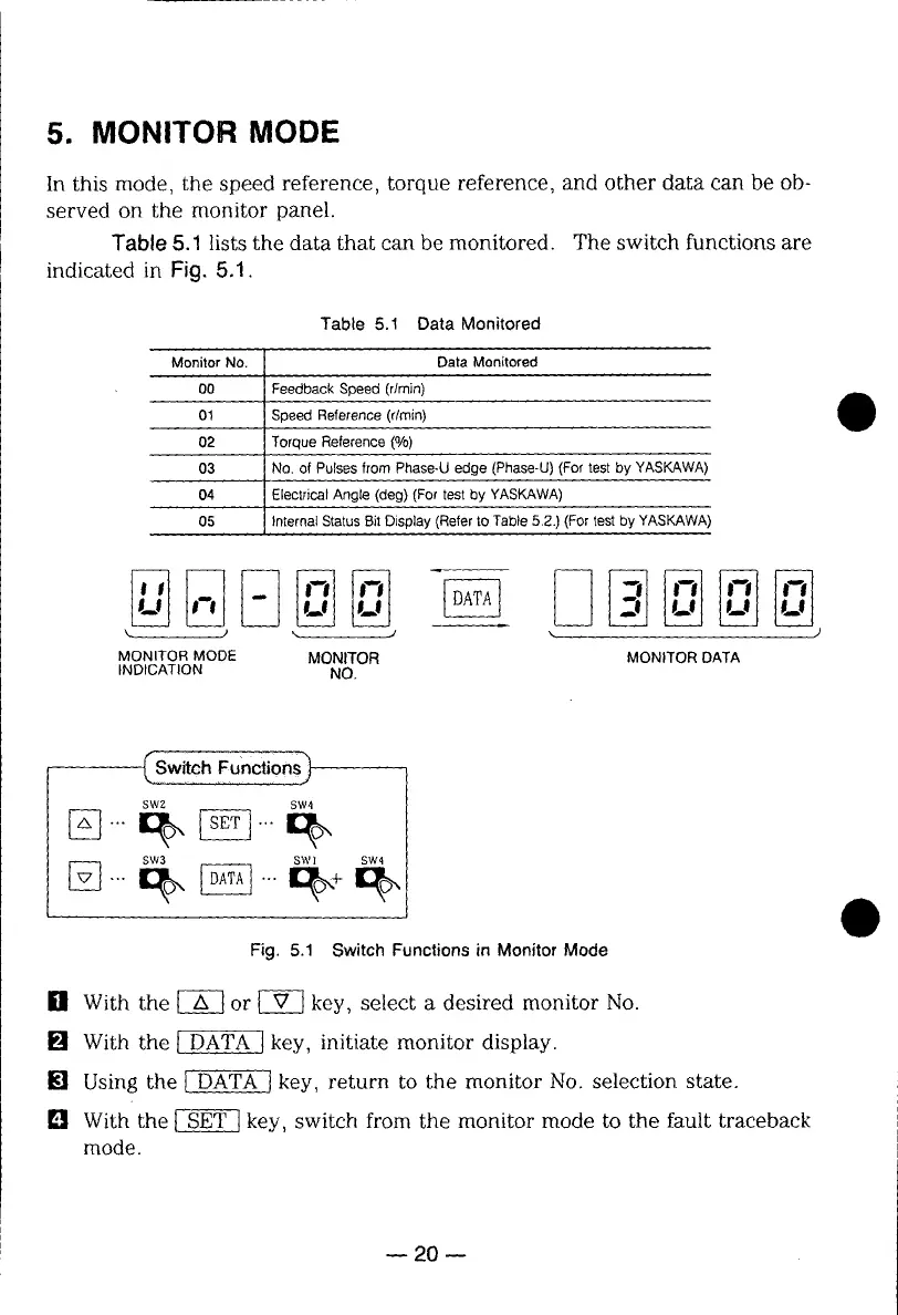
5. MONITOR MODE
In this mode, the speed reference, torque reference, and other data can be ob-
served on the monitor panel.
Table 8.1 lists the data that can be monitored. The switch functions are
indicated in Fig. 5.1.
Table 5.1 Data Monitored
Monitor No. Data Monitored
00 Feedback Speed (r/min)
01 Speed Reference (r/rain)
02 Torque Reference (%)
03 No. of Pulses from Phase-U edge (Phase-U) (For test by YASKAWA)
04 Electrical Angle (deg) (For test by YASKAWA)
05 Internal Status Bit Display (Refer to Table 5.2.) (For test by YASKAWA)
M ) ',. J _. . )
MONITORMODE MONITOR MONITORDATA
INDICATION NO.
[]
Fig. 5.1 Switch Functions in Monitor Mode
ill With the _ or _ key, select a desired monitor No.
[] With the _ key, initiate monitor display.
[] Using the _ key, return to the monitor No. selection state.
[] With the _ key, switch from the monitor mode to the fault traceback
mode.
20 m
 Loading...