7.3 Flux Vector Control
7-21
7.3.3 Torque Control
J
Torque Control Function Settings: d5-01
With flux vector control, the motor’s output torque can be controlled by a torque reference from an analog
input.
User
Change
Valid Access Levels
Constant
Number
Name
during
Opera-
tion
Setting
Range
Unit
Factory
Setting
V/f
Control
V/f with
PG
Open
Loop
Vector
Flux
Vector
d5-01
Torque control selec-
tion
×
0, 1 − 0
× × ×
A
D
Settings
Setting Function
0
Speed control (controlled by C5-01 to C5-07)
1
Torque control
D
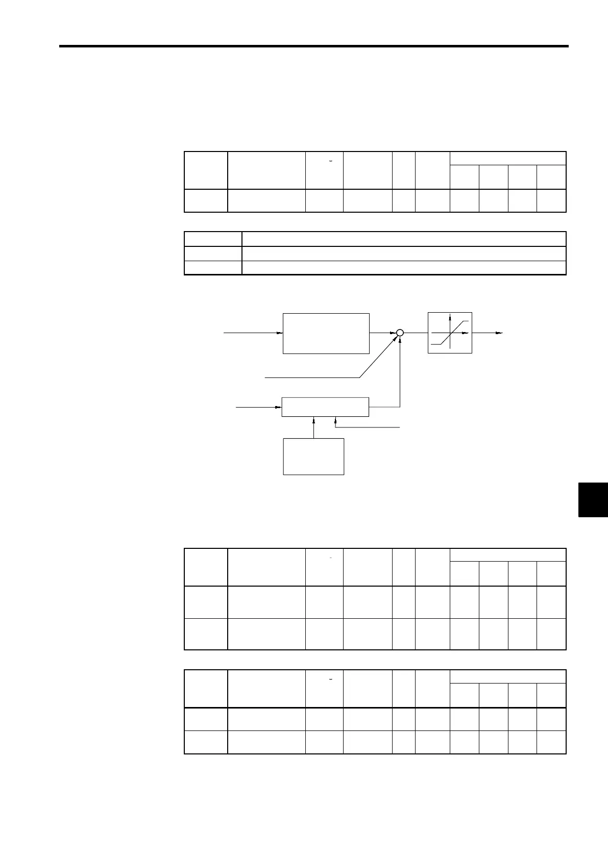
Set constant d5-01 to “1” to select torque control.
D
Figure 7.10 shows the operation of torque control.
Torque reference
Torque reference
primary delay filter
(d5-02)
+
+
+
Torque limit
(L7-01 to L7-04)
Torque compensation
Speed limit
Speed limiting circuit
Speed limit
bias (d5-05)
Speed feedback
Internal torque
reference
Fig
7.10
Torque Control Block Diagram
J
Torque Reference Settings: H3-04, H3-05, H3-08, H3-09
D
Set the multi-function analog input terminal 16 (H3-05) or 14 (H3-09) to torque reference (a setting
of 13). The torque reference value cannot be set with the Digital Operator.
User
Change
Valid Access Levels
Constant
Number
Name
during
Opera-
tion
Setting
Range
Unit
Factory
Setting
V/f
Control
V/f with
PG
Open
Loop
Vector
Flux
Vector
H3-05
Multi-function ana-
log input (terminal
16)
×
0to1F − 0
B B B B
H3-09
Multi-function ana-
log input (terminal
14)
×
1to1F − 1F
A A A A
D
Next, set the signal level for the analog input terminal that was set to torque reference.
User
Change
Valid Access Levels
Constant
Number
Name
during
Opera-
tion
Setting
Range
Unit
Factory
Setting
V/f
Control
V/f with
PG
Open
Loop
Vector
Flux
Vector
H3-04
Signal level selec-
tion (terminal 16)
×
0, 1 − 0
B B B B
H3-08
Signal level selec-
tion (terminal 14)
×
0to2 − 2
A A A A
7
 Loading...