8.5 Relay Encoder Cable of 30 m to 50 m
8.5.2 Encoder Cables for SGM7E and SGM7F Servomotors
8
Cables and User-Assembled Wiring Materials for Direct Drive Servomotors
8-31
8.5.2
Encoder Cables for SGM7E and SGM7F Servomotors
For flange specification 1 or 3, use a Motor-End Relay Encoder Cable and a SERVOPACK-End
Relay Encoder Cable. For flange specification 4, use only a SERVOPACK-End Relay Encoder
Cable.
If a battery is not mounted to the host controller, also obtain a Relay Encoder Cable with a Bat-
tery Case in addition to the above Cables.
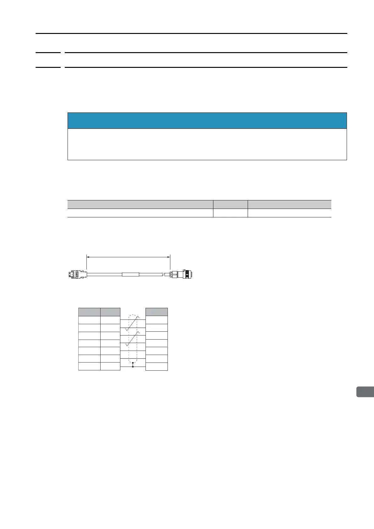
Motor-End Relay Encoder Cables
Selection Table
Note: Flexible cables are not available.
External Dimensions
Wiring Specifications
* A battery is required only for a multiturn absolute encoder.
Note: Always connect the shield wire from the Encoder Cable to the connector case (shell).
Install a battery at either the host controller or on the Encoder Cable.
If you install batteries both at the host controller and on the Encoder Cable at the same time,
you will create a loop circuit between the batteries, resulting in a risk of damage or burning.
Specification Length (L) Order Number
For incremental or multiturn absolute encoder 0.3 m JZSP-C7PRC0-E
Encoder endSERVOPACK end
L
Pin
8*
1
5*
2
9
4
Encoder (motor) end
Pin Signal
6
5
4
3
2
1
Shell FG
7
SERVOPACK end
Shield wire
/PS
PS
BAT0
BAT
PG5V
PG0V
 Loading...


