4 CANopen Lift Option Components
YASKAWA ELECTRIC SIEP YEUOCL1 01A CANopen-Lift Communication Option Installation Manual 11
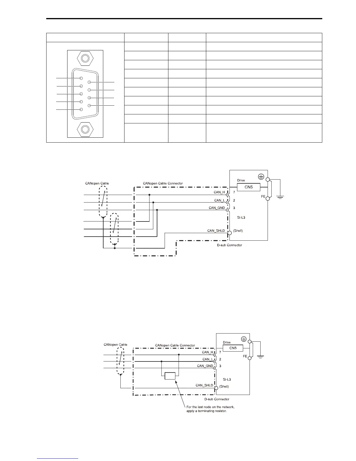
Table 4.1 Pin Assignment
Connector Pin Signal Description
1 – –
2 CAN_L CAN_L bus line (dominant low)
3 CAN_GND CAN ground
4 – –
5 CAN_SHLD CAN shield
6 – –
7 CAN_H CAN_H bus line (dominant high)
8 – –
9 – –
– CAN_SHLD CAN shield
■ Communication Cable
Connect the CANopen-Lift option card to the network using a 9 pin D-sub connector wired like shown below.
Figure 4.3 Wiring Diagram
Note:
The FE terminal on the Communication Option must be connected to the drive ground terminal using the delivered ground wire.
■ Network Termination
Both ends of the CANopen network have to be terminated with a 120 Ohm resistor. If the CANopen option is the
last node in the network, make sure to apply a termination resistor as shown below, because the CANopen option
does not have a built-in termination resistor:
Figure 4.4 Termination Resistor

 Loading...


