5 Installation Procedure
YASKAWA ELECTRIC TOBP C730600 89D YASKAWA AC Drive Option SI-EP3 Installation Manual 27
n Procedure B
This section shows the procedure to install and wire the option on a GA700 or GA800 drive.
Prepare the Drive for the Option
Before you install the option on a YASKAWA AC Drive GA700 or GA800, make sure that
the option software version is PRG: 4400 or later.
1. Correctly wire the drive as specified by the manual packaged with the drive.
2. Make sure that the drive functions correctly.
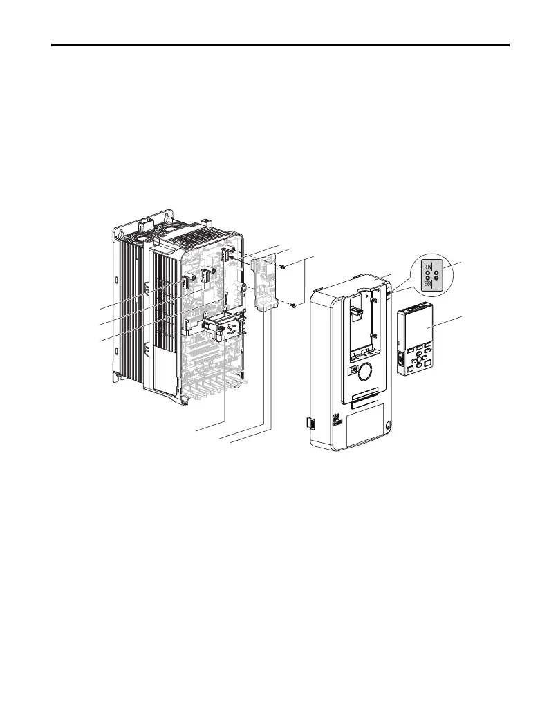
Refer to Figure 11 for an exploded view of the drive with the option and related
components for reference in the installation procedure.
Figure 11
Figure 11 Drive Components with Option
A – Insertion point for CN5 connector I – LED Status Ring board
B – SI-EP3 option J – Connector CN5-A
C – Included screws K – Connector CN5-B
(Not available for communication
option installation.)
D – Drive front cover
E – LED label
F – Keypad L – Connector CN5-C
(Not available for communication
option installation.)
G – Option modular connector CN1
port 1
H – Option modular connector CN2
port 2
GEM_PROFINET_IM_E_conditional.book 27 ページ 2019年2月21日 木曜日 午後3時37分