5 Installation Procedure
32 YASKAWA ELECTRIC TOBP C730600 89D YASKAWA AC Drive Option SI-EP3 Installation Manual
7.
Reattach the LED Status Ring board (I).
Use the open space provided inside the LED Status Ring board to route option
wiring.
NOTICE: Do not pinch cables between the front cover or the LED Status Ring board and the drive. Failure
to comply could cause erroneous operation.
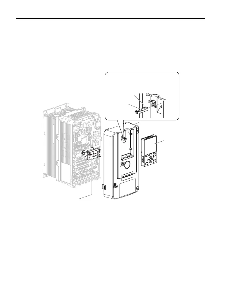
8.
Reattach the drive front cover (D) and the keypad (F).
Figure 16
Figure 16 Replace the Front Cover and Keypad
9.
Set drive parameters in Table 7 for correct option performance. Be sure to set
parameter F6-30 to a node address unique to the network.
D
F
I
Install the keypad to the drive after replacing
the keypad connector and then the keypad
connector. At that time, insert the keypad
connector tab into the drive.
Keypad
connector
Tab
GEM_PROFINET_IM_E_conditional.book 32 ページ 2019年2月21日 木曜日 午後3時37分