5 Installation Procedure
YASKAWA ELECTRIC TOBP C730600 89D YASKAWA AC Drive Option SI-EP3 Installation Manual 31
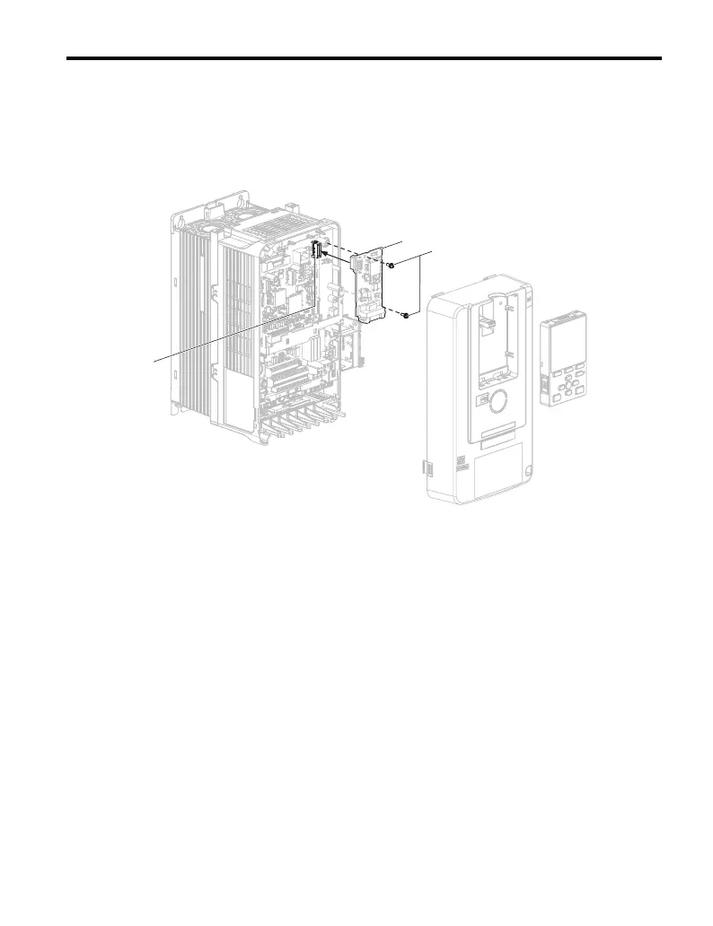
4.
Insert the option card (B) into the CN5-A connector (J) on the drive and fasten it into
place using the included screws (C). Tighten both screws to 0.5 to 0.6 Nm (4.4 to
5.3 inlb).
Note: Only two screws are necessary to install the option on a GA700 or GA800 drive. A ground wire
is not necessary. The option package ships with three screws and a ground wire for installation
on other product series. Do not use the ground wire or the extra screw.
Figure 15
Figure 15 Insert the Option Card
5.
Firmly connect the PROFINET Cat 5e communication cable to the option modular
connector CN1 port 1 or port 2. Install PROFINET communications cables apart
from main-circuit wiring and other electrical and power lines. Ensure the cable end
is firmly connected (see Figure 17). Refer to Communication Cable
Specifications on page 33 for details of installing.
Note: 1. Separate communication cables from main circuit wiring and other electrical lines.
2. Do not connect or disconnect the communication cable while the drive is powered up or while the drive
is in operation. Failure to comply may cause a static discharge, which will cause the option card to stop
working properly. Cycle power on the drive and option card to reestablish functionality.
3. Maximum transmission distance is 100 m (328 ft). Minimum wiring distance between stations is 0.2 m
(7.9 in).
6.
Use the second option modular connector CN1 port to daisy chain a series of drives
where applicable.
C
B
J
GEM_PROFINET_IM_E_conditional.book 31 ページ 2019年2月21日 木曜日 午後3時37分