4 Inputs and Outputs
4.4.1 Using a Rotary Servo Motor
25
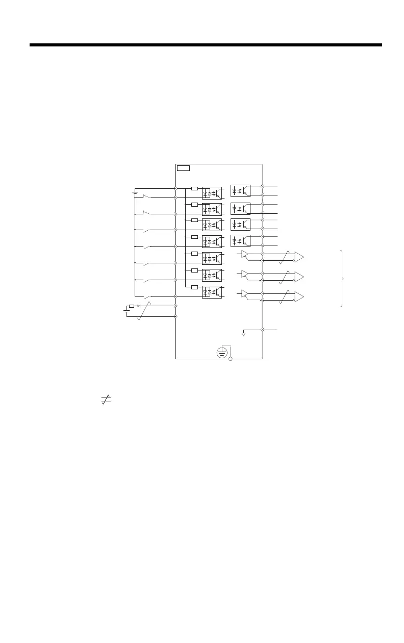
4.4 I/O Signal Wiring Examples
4.4.1 Using a Rotary Servo Motor
200 V SERVOPACKS
* 1. represents twisted-pair wires.
* 2. Connect these when using an absolute encoder. If the Encoder Cable with a Battery Case
is connected, do not connect a backup battery.
* 3. The 24-VDC power supply is not provided by Yaskawa. Use a 24-VDC power supply with
double insulation or reinforced insulation.
* 4. Always use line receivers to receive the output signals.
Note: 1. You can use parameters to change the functions allocated to the /SI0, /SI3,
P-OT, N-OT, /EXT1, /EXT2, and /EXT3 input signals and the /SO1, /SO2,
and /SO3 output signals.
2. If you use a 24-V brake, install a separate power supply for the 24-VDC
power supply from other power supplies, such as the one for the I/O signals
of the CN1 connector.
If the power supply is shared, the I/O signals may malfunction.
/BK+
/BK-
/SO2+
/SO2-
/SO3+
ALM+
ALM-
1
2
23
24
3
4
+24VIN
+24 V
*3
4.7 k
Ω
6
8
10
9
11
12
/SI0
P-OT
N-OT
General-purpose
digital input 0
BAT+
BAT-
13
14
15
7
/SO3-
Forward Drive Prohibit input
(prohibited when OFF)
Digital input signal
power supply input
Battery for
absolute encoder
Backup battery
*2
2.8 V to 4.5 V
Reverse Drive Prohibit input
(prohibited when OFF)
Brake output
(released when ON)
Servo Alarm Output
(OFF for alarm)
25
26
16
SG
*1
PBO
PCO
/PBO
PAO
/PAO
/PCO
21
17
18
19
20
22
FG
CN1
*4
*4
*4
Photocoupler outputs
Max. allowable voltage: 30 VDC
Max. allowable current: 50 mA DC
Encoder Divided
Pulse Output,
Phase A
Encoder Divided
Pulse Output,
Phase B
Encoder Divided
Pulse Output,
Phase C
Applicable Line
Receiver:
SN75ALS175 or
MC3486
manufactured
by Texas
Instruments or
the equivalent
Connect shield to connector shell.
Connector
shell
SERVOPACK
Frame ground
Signal ground
/SI3
/EXT1
/EXT2
/EXT3
External latch signal 1 input
(General purpose input 4)
General-purpose
digital input 3
General-purpose
digital input 5
General-purpose
digital input 6
+
-