Application •
5.8.1 Holding Brake Interlock Signal
5.8 Appropriate Applications
5.8.1 Holding Brake Interlock Signal
This output signal can be output for interlocking motor circuit power status and motor rotation
speed.
■ Setup Procedure
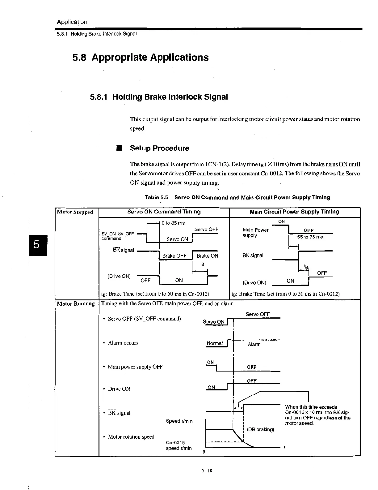
The brake signal is output from 1CN-1(2). Delay time tB ( X 10 ms) from the brake turns ON until
the Servomotor drives OFF can be set in user constant Cn-0012. The following shows the Servo
ON signal and power supply timing.
Table 5.5 Servo ON Command and Main Circuit Power Supply Timing
Motor Stopped
Servo ON Command Timing
Main Circuit Power Supply Timing
SV ON SV_OFF
command
BK signal
(Drive ON)
0 to 35 ms
Servo ON
Servo OFF
Brake OFF
OFF I ON
Brake ON
tg
P
tB: Brake Time (set from 0 to 50 ms in Cn-0012)
ON
Main Power 1 OFF
supply 5 to 75 ms
BK signal
(Drive ON)
tB
OFF
ON I
tg: Brake Time (set from 0 to 50 ms in Cn-0012)
Motor Running
Timing with the Servo OFF, main power OFF, and an alarm
• Servo OFF (SV_OFF command)
• Alarm occurs
• Main power supply OFF
• Drive ON
• BK signal
Speed r/min
• Motor rotation speed
Cn-0015
speed r/min
Servo OFF
Servo ON'
Normal
ON
0
Alarm
OFF
OFF
ON
(DB braking)
When this time exceeds
Cn-0016 x 10 ms, the BK sig-
nal turn OFF regardless of the
motor speed.
5 -18
 Loading...