EasyManuals Logo

YASKAWA V1000 Series Option Manual

YASKAWA V1000 Series
26 pages
To Next Page IconTo Next Page
To Previous Page IconTo Previous Page
Page #13 background imageLoading...
Page #13 background image
u
External Heatsink Option Installation Procedures
n
Procedure 1 (Enclosure: IP20)
1. Remove the front cover according to the drive instruction manual.
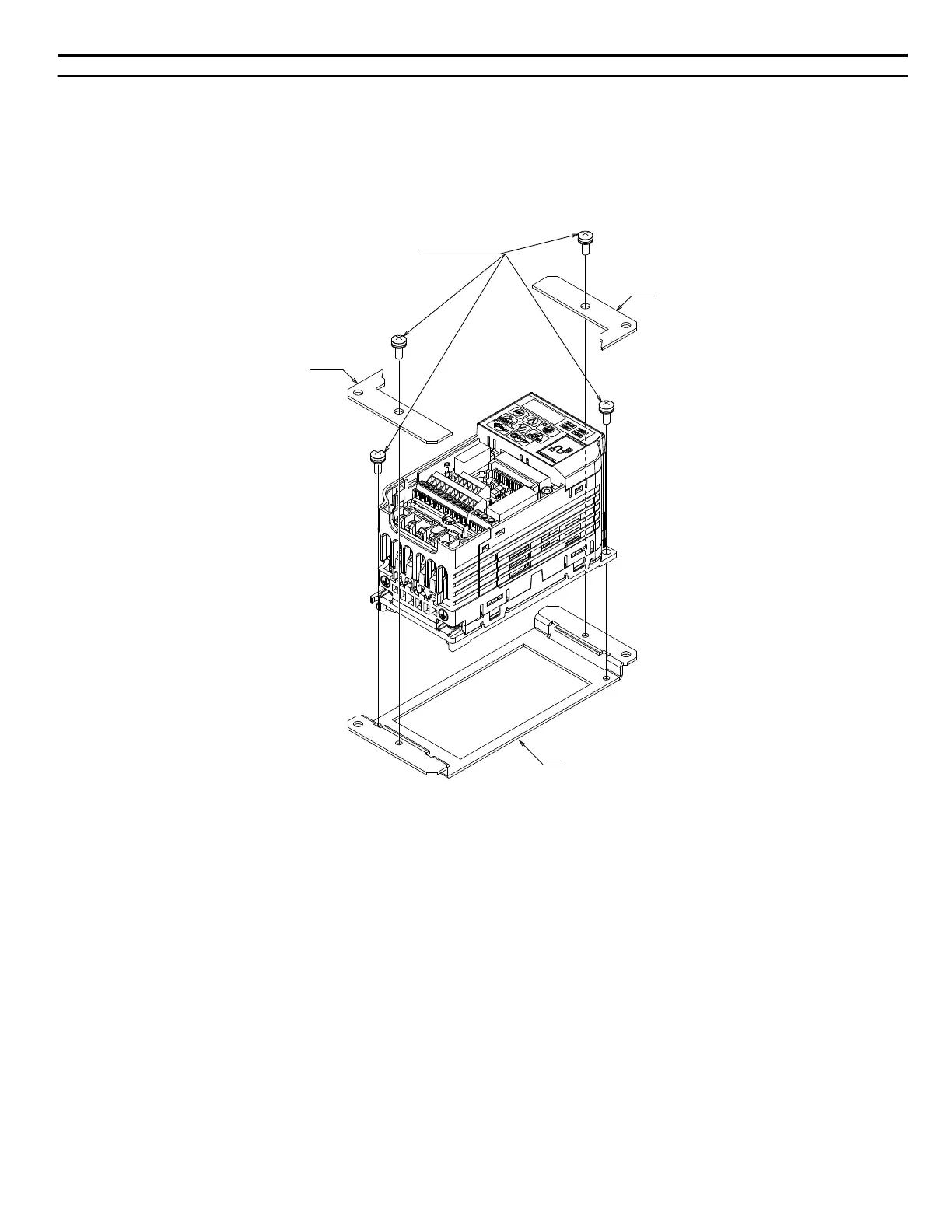
2. Mount Attachment A to the standard drive mounting legs using the associated M4×10 pan-head screws.
3. Mount Attachment B (2 units) to Attachment A with the associated M4×10 pan-head screws as shown in Figure 3.
4. Reattach the front cover according to the drive instruction manual.
Attachment B
Attachment A
Attachment B
M4x13 Pan-head Screws (x4)
Figure 3 Procedure 1 Diagram (Example Model: CIMR-Vo2o0001)
5 Installation Procedure by Drive Model
YASKAWA V1000/J1000 AC Drive External Heatsink Kit Option Manual EZZ020568
13

Other manuals for YASKAWA V1000 Series

Questions and Answers:

Question and Answer IconNeed help?

Do you have a question about the YASKAWA V1000 Series and is the answer not in the manual?

YASKAWA V1000 Series Specifications

General IconGeneral
ModelV1000 Series
SeriesV1000
Output Frequency0.1 to 400 Hz
Overload Capacity150% for 60 seconds
TypeAC Drive
Control MethodV/f Control
Input Voltage200-240V, 380-480V
Output Voltage0 to Input Voltage
Power Range0.1 to 18.5 kW
Horsepower0.2 to 25 HP
Protection FeaturesOvercurrent, Overvoltage, Undervoltage, Overheating, Short Circuit, Ground Fault
Communication InterfacesModbus RTU
EnclosureIP20
Ambient Temperature-10 to +50°C
Storage Temperature-20 to +60°C
Humidity5 to 95% RH (non-condensing)
Cooling MethodFan Cooled

Related product manuals